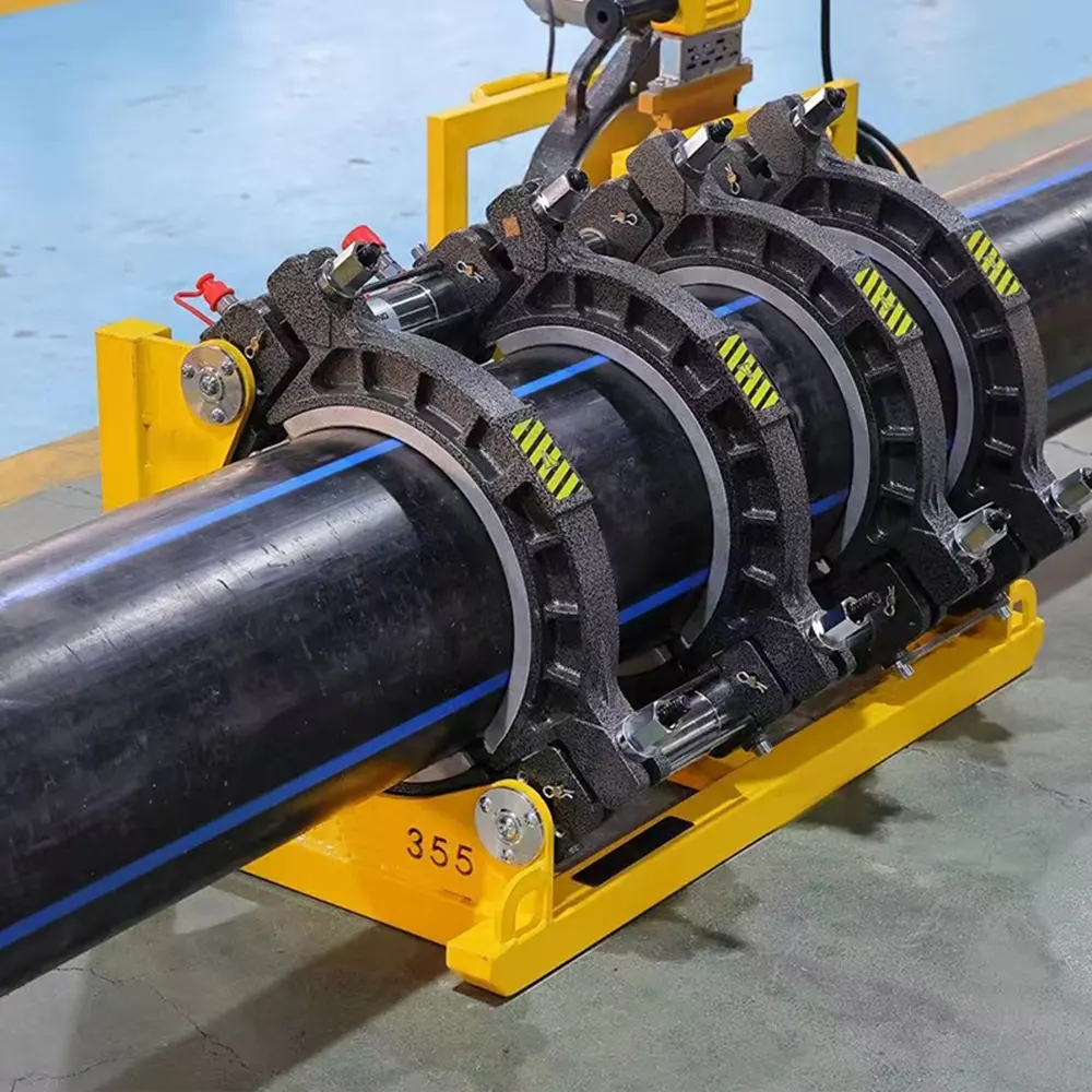
Accurate HDPE pipe welding productivity calculation is the cornerstone of efficient project management in modern pipeline construction. Whether you are working on a municipal water supply network, a gas distribution system, or an industrial mining pipeline, understanding the exact output you can achieve per shift directly impacts your bid accuracy, resource allocation, and ultimate profitability. This comprehensive guide breaks down the essential methods, core formulas, and field-tested best practices to help you master the calculation of welding productivity, ensuring your operations run at peak performance while maintaining the integrity of every joint.
Understanding the Basics of HDPE Welding Productivity
Before diving into complex formulas, it is crucial to define what productivity truly means in the context of butt fusion operations. Simply put, productivity is not just the number of welds completed per day; it is the total length of pipeline installed over a specific period, factoring in the complete jointing cycle. The calculation must account for the entire welding cycle, which includes the facing, heating, bead-up, and cooling phases. Ignoring any of these stages, particularly the mandatory cooling time under pressure, will lead to overly optimistic projections and potentially compromise the mechanical properties of the joint.
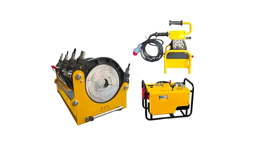
According to the PPI butt fusion procedure, the standardized parameters are essential to achieving a reliable weld. The interface pressure, heater plate temperature, and bead sizes are all variables that, while fixed by standards such as ISO 21307 butt fusion procedures, directly influence the cycle time. For high-volume projects, making the correct choice between manual, hydraulic, and CNC automatic systems is the first and most impactful decision affecting your overall output rate.
| Machine Type | Typical Pipe Range (mm) | Approx. Cycle Time (D250 SDR11) | Average Joints per Hour |
|---|---|---|---|
| Manual Butt Fusion | 63 – 315 | 18 – 25 min | 2 – 3 |
| Hydraulic Butt Fusion | 160 – 2250 | 20 – 30 min | 1.5 – 2.5 |
| CNC Automatic | 160 – 1200 | 15 – 22 min | 2.5 – 4 |
The Core Formula for Welding Productivity Calculation
To translate the machine cycle into a practical HDPE pipe welding productivity calculation, contractors rely on a universal formula that bridges machine time with installed pipeline length. The primary equation is:
Daily Productivity (Meters) = (Pipe Length per Joint) × (Number of Joints per Day)
Where:
- Pipe Length per Joint: Typically 6, 12, or 18 meters, depending on the coil or stick length delivered to the trench.
- Number of Joints per Day: (Total Effective Working Minutes per Day) / (Total Cycle Time per Weld in Minutes)
- Total Cycle Time: Heating Time + Bead-Up Time + Cooling Time + Machine Handling Time
For a precise calculation, the cooling time cannot be estimated. It is a strict function of the pipe wall thickness. The standardized cooling time ensures the molten interface solidifies completely before the pipes are removed from the clamps. Releasing the pressure too early, a common mistake when rushing for output, results in a weakened joint. For advanced data tracking, systems adhering to PE fusion traceability can automatically log these cycle parameters for quality assurance reporting.
Key Factors Influencing HDPE Welding Output Rates
While the mathematical model is straightforward, real-world site conditions heavily modify the theoretical output. An effective HDPE pipe welding productivity calculation must adjust for these practical variables to avoid cost overruns.
1. The Impact of Pipe Diameter and Wall Thickness
This is the most significant variable. The relationship between diameter and cycle time is not linear; it is primarily driven by the Standard Dimension Ratio (SDR). A lower SDR number indicates a thicker wall, which requires a substantially longer cooling cycle to dissipate the heat. For example, while a D200 SDR17 pipe may cool within 10 minutes, a D200 SDR11 pipe can require over 16 minutes under the same ambient conditions. Therefore, using a single average time for all SDRs on a project is a critical error in productivity planning.
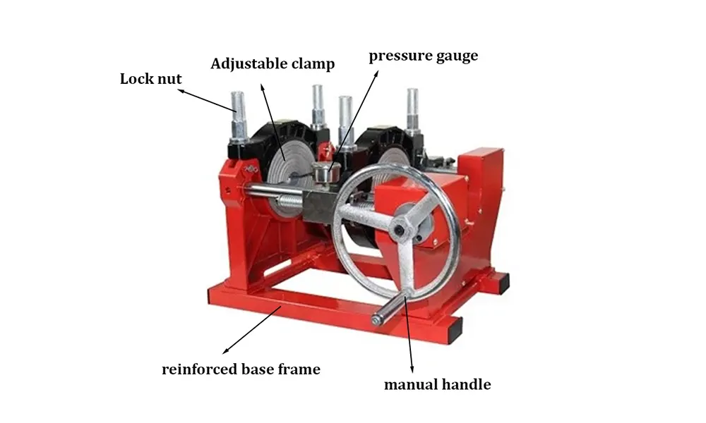
2. Machine Automation and Clamping Efficiency
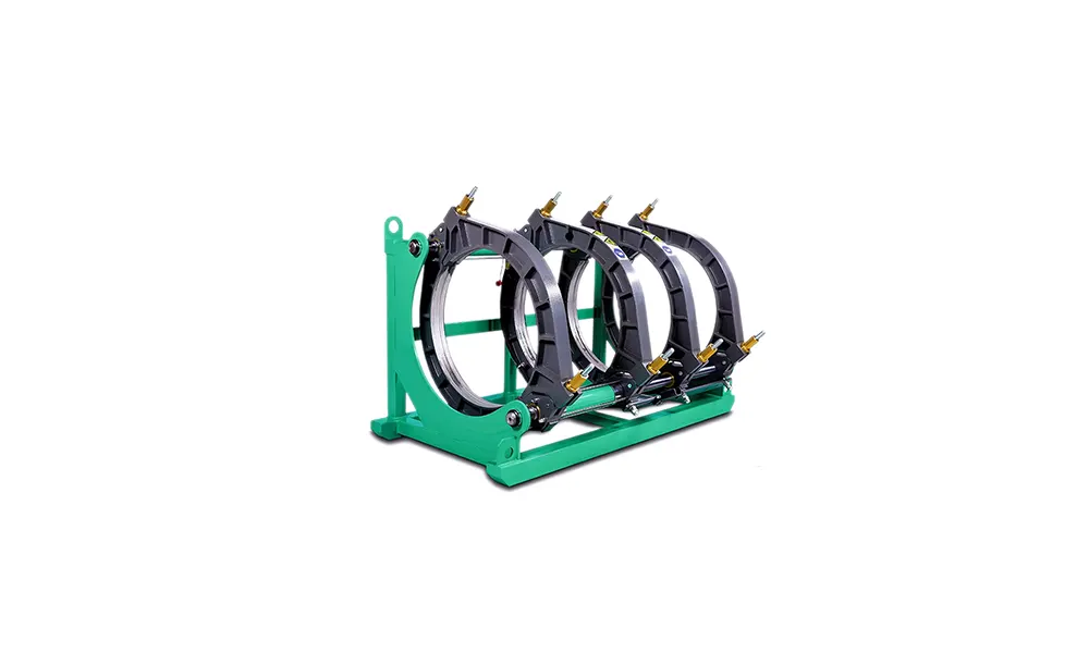
The choice of equipment dramatically alters the handling time component of the cycle. Manual machines require physical effort to lock the clamps, face the pipes, and engage the hydraulic hand pump, adding significant seconds or even minutes to every joint. Conversely, CNC automatic machines execute these steps with servomotors in a fraction of the time, with perfect repeatability. JQ-Fusion, as a specialized manufacturer, designs hydraulic and automatic systems that optimize clamp movement speed without sacrificing alignment precision, effectively compressing the ‘open-close’ window of the cycle.
3. Operator Skill and Crew Coordination
A skilled operator achieves a consistent bead throughout the pipe circumference on the first attempt, eliminating the need for a second facing pass. The coordination between the machine operator and the pipe handler (excavator or crane) is just as critical. If the machine sits idle waiting for the next pipe stick to be lowered into the clamps, productivity plummets. These waiting times must be factored into the realistic daily rates. Certification to meet PE fusion operator requirements is a strong indicator of an operator’s ability to minimize these delays.
4. Environmental Conditions
Extreme cold, strong winds, and heavy dust introduce challenges that the base formula overlooks. Wind chill accelerates the cooling of the heater plate surface, potentially requiring a slight overshoot in the set temperature, while very low ambient ground temperatures can reduce the required cooling times marginally—though this must never be guessed. Sand and dust ingress on the pipe surface demand meticulous cleaning, adding time to the pre-weld preparation phase.
Step-by-Step Guide to Calculating Project Output
To implement this for your next tender or site plan, follow this structured sequence. We will use a practical example of laying a 500-meter section of D315 SDR17 pipe using a hydraulic machine.
- Determine the Total Cycle Time: Consult the machine’s data logging for recent joints under similar conditions. Assume a total cycle of 20 minutes for D315 SDR17.
- Calculate Joints Per Hour: 60 minutes / 20 minutes per joint = 3 joints per hour.
- Calculate Hourly Installation Rate: If using 12-meter pipe lengths: 3 joints/hour × 12 meters = 36 meters per hour.
- Apply the Downtime Factor: Deduct non-productive time. A commonly used efficiency factor is 70% – 85%. Assuming 80% efficiency, the effective hourly rate is 36 meters × 0.80 = 28.8 meters per hour.
- Calculate Daily Output: For an 8-hour shift, 28.8 meters/hour × 8 hours = 230.4 meters per day.
Pro Tip: Always calculate productivity based on linear meters per day, not joints per day. This accounts for the use of shorter pipe lengths in crossing under obstacles or for tie-in sections, where the number of joints per meter increases significantly.
Advanced Calculation Methods and Data Logging
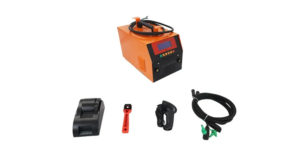
Modern projects increasingly demand data-driven productivity reporting. High-end hydraulic butt fusion welding machines equipped with intelligent data loggers allow you to export the exact timeline of every weld. This gives an actual average cycle time over hundreds of joints, rather than a textbook estimate. Using this archived data, you can prove to project owners that your calculated productivity rates are based on verifiable historical performance. This data also supports compliance with ASTM F2620 heat fusion recording requirements.
Optimizing Productivity Without Sacrificing Joint Integrity
The goal of a refined HDPE pipe welding productivity calculation is to find the balance between speed and specification compliance. Never attempt to shortcut the cooling cycle; instead, focus your optimization efforts on the margins of the process. Pre-loading the next pipe stick into a roller rack while the current joint is cooling is a zero-cost method to eliminate handling time. Maintaining sharp facer blades reduces the time needed to square the pipe ends. Furthermore, routine calibration of the heater plate temperature distribution ensures you are not operating with cold spots that slow down the heat soak phase.
Conclusion: Turning Calculation into Competitive Advantage
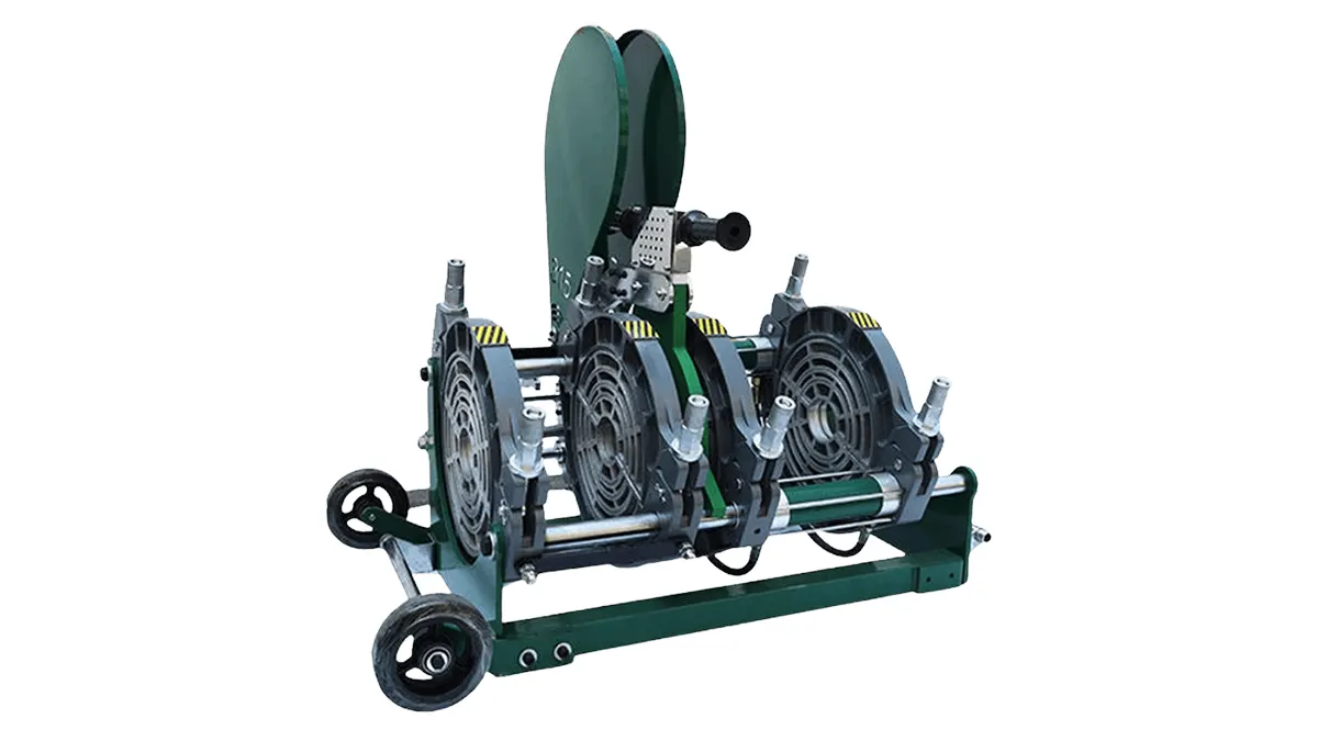
Mastering the HDPE pipe welding productivity calculation transforms your bidding process from a guessing game into a precise science. By distinguishing between theoretical cycle times and real-world efficiency factors, and by investing in efficient equipment like CNC automatic welding machines that reduce manual handling delays, contractors can safely increase their daily installation averages. Remember, true productivity is measured not by the number of joints made, but by the number of defect-free, tested meters of pipeline installed per shift. Using the methods and formulas outlined above, you can ensure your pipeline projects stay on schedule, within budget, and to the highest standards of PE pipe joining.
For teams requiring reliable and fast-cycle machinery to meet these calculated targets, exploring the full range of butt fusion solutions can provide the mechanical foundation necessary for high-output projects. The right machine, combined with a sharp calculation model, is the blueprint for pipeline construction success.