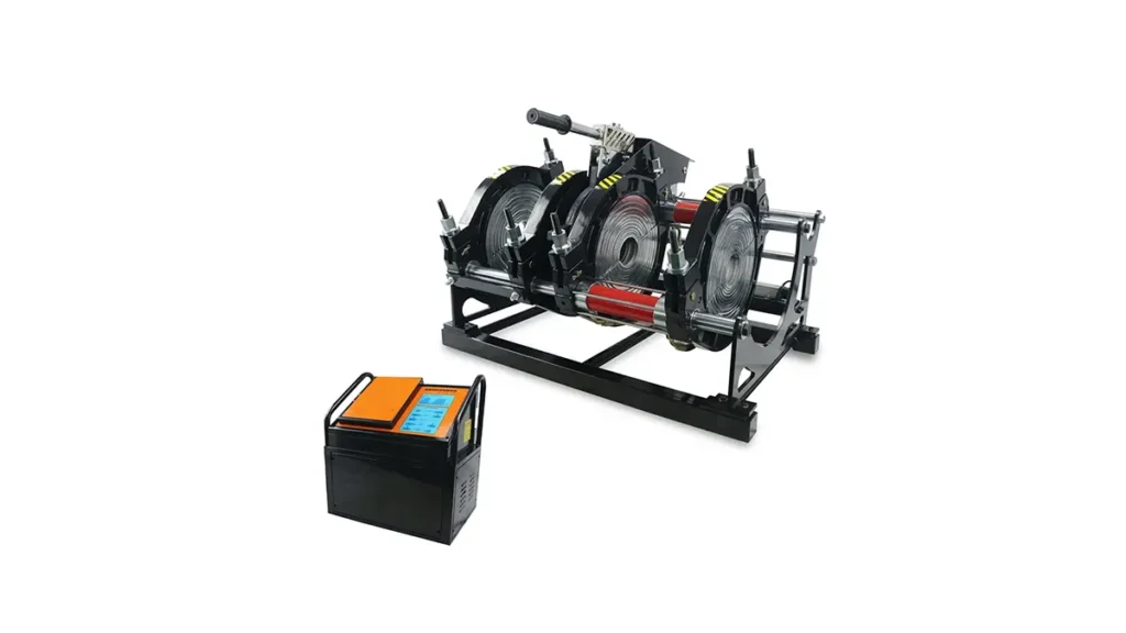
Achieving a perfect, leak-free joint in High-Density Polyethylene (HDPE) piping systems depends heavily on one critical variable: the welding pressure. Incorrect pressure can lead to weak bonds, excessive melt bead, or cold joints that fail under pressure. This guide breaks down the science behind HDPE pipe welding machine pressure settings, helping operators and project managers optimize their butt fusion procedures to meet international standards.
Why Pressure Matters in HDPE Butt Welding
The butt fusion process requires a specific inter-facial pressure to ensure the melted pipe ends mix correctly and form a homogeneous joint. Too little pressure, and the molten material won’t intermix; too much, and all the heated material squeezes out, creating a cold weld. The goal is to maintain a consistent bead size while following the ISO 21307 butt fusion procedures.
Understanding the Three Pressure Phases
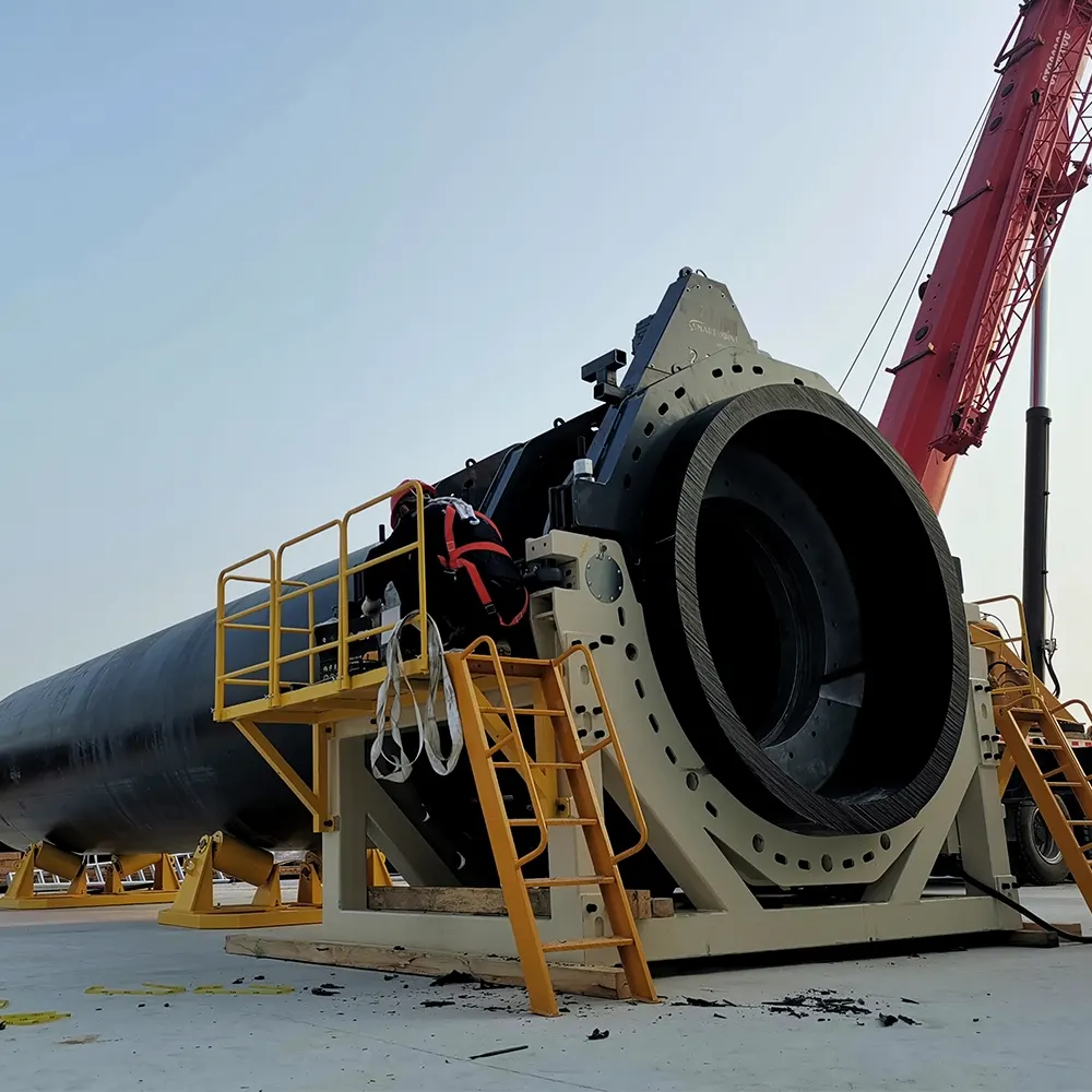
Standard ASTM F2620 heat fusion standards define three distinct pressure stages during a weld cycle. Failing to switch between these stages accurately is a common cause of joint failure.
| Phase | Action | Pressure Requirement |
|---|---|---|
| Bead-Up | Initial contact with the heater plate | High pressure (typically 0.15 MPa + drag) |
| Heat Soak | Heat penetration without material movement | Near-zero pressure (drag only) |
| Fusion/Cooling | Joining the melted ends and solidifying | Steady buildup to 0.15 MPa (held solid) |
How to Calculate Gauge Pressure for Your Machine
A common mistake is confusing interfacial pressure with gauge pressure. You don’t set the theoretical 0.15 MPa (for PE80/PE100) directly on the machine gauge. Instead, you must calculate the actual hydraulic pressure required to overcome pipe drag and the machine’s internal resistance.
Step-by-Step Calculation
- Standard Interfacial Force: 0.15 N/mm² (per ISO 21307).
- Total Piston Area: Sum of the effective areas in your machine’s hydraulic cylinders.
- Drag Pressure: The pressure needed to move the pipe without heating (record this value before welding).
- Formula: Weld Pressure = (Interfacial Force x Pipe Area) / Total Piston Area + Drag Pressure.
Pressure Settings by Welding Machine Type
The method of applying pressure varies significantly between manual, hydraulic, and CNC automatic machines.
| Machine Type | Pressure Control | Best For |
|---|---|---|
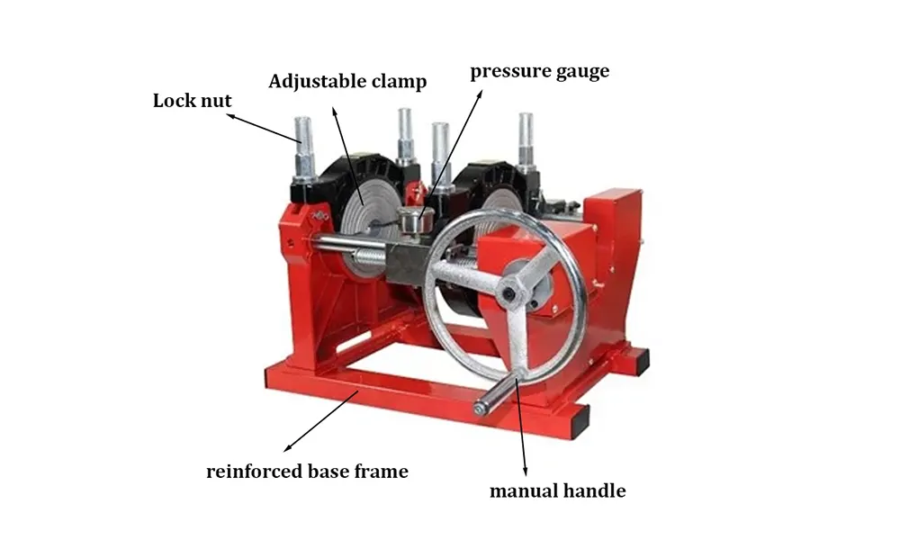
| Manual Machines | Hand-lever force (operator skill dependent) | Small diameters, field repairs |
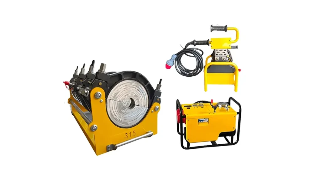
| Hydraulic Machines | Manual hydraulic valve & gauge | Medium to large diameters, precise control |
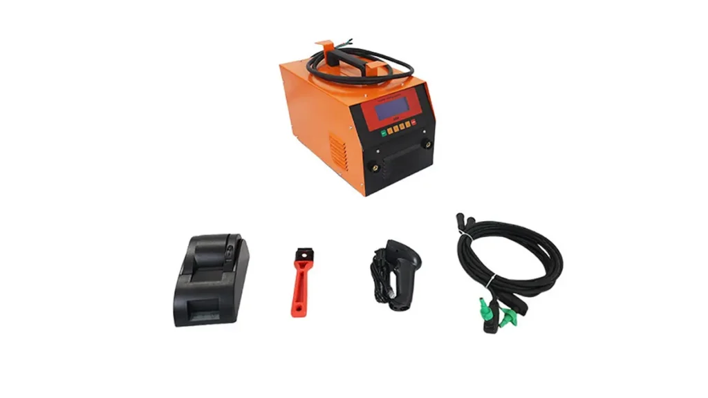
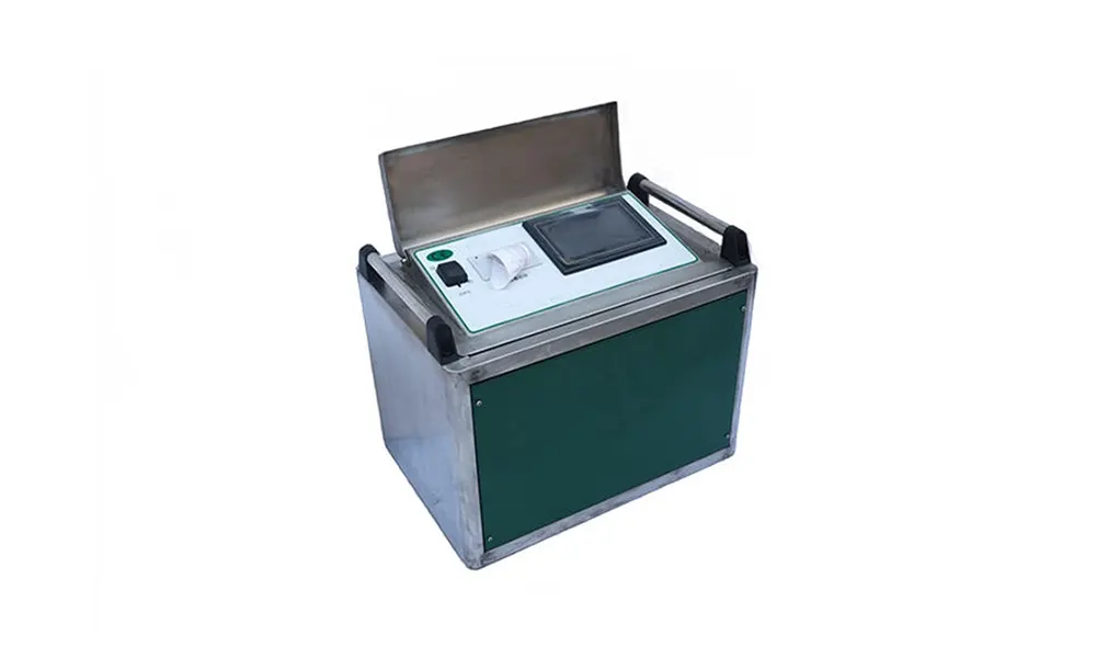
| CNC Automatic Machines | Servo-hydraulic, automatic calculation | Critical gas/water mains, data logging |
Critical Drag Pressure Measurement
Before every weld, the drag pressure must be measured. This tells the operator how much force is wasted on friction within the machine and the pipe supports. To measure it, move the pipe without the heater at a constant speed and note the pressure reading. This “drag” is added to the theoretical weld pressure. PPI butt fusion procedure documents emphasize that skipping this step is the primary cause of low-strength joints.
Avoiding Common Pressure Mistakes
- Mistake 1: Ignoring Ambient Temperature – Cold weather requires slightly longer soak times, but the fusion pressure remains calculated; do not over-pressurize to compensate.
- Mistake 2: Wrong Cylinder Area – Machines with multiple cylinders need the total area, not just one. This leads to pressure being set dangerously low.
- Mistake 3: Moving Pipes During Cooling – Pressure must be maintained until the joint cools below its melt point. Any movement creates residual stress fractures.
Quick Reference for Common Pipe Sizes
The table below provides typical theoretical interfacial pressure ranges. Always refer to your specific machine’s manual for the conversion to gauge pressure.
| Pipe Diameter | Wall Thickness (SDR 11) | Approx. Interfacial Force Required (N) |
|---|---|---|
| 110 mm | 10 mm | ~518 N |
| 200 mm | 18.2 mm | ~1,560 N |
| 315 mm | 28.6 mm | ~3,860 N |
| 500 mm | 45.4 mm | ~9,700 N |
The Role of Durable Machinery in Maintaining Pressure
Consistent HDPE pipe welding machine pressure settings are impossible to achieve with leaky hydraulics or worn-out clamps. Hydraulic butt fusion welding machines with aluminum clamps offer the rigidity needed to prevent pipe slippage, which directly translates to accurate, stable pressure throughout the cooling cycle.
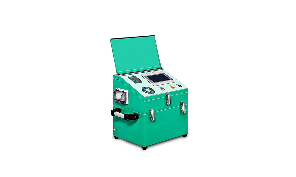
For reliable, high-performance butt welds, using a properly calibrated machine with strict adherence to pressure protocols is non-negotiable. As a professional supplier, JQ-Fusion provides a range of hydraulic and automatic welding machines designed to maintain precise welding parameters even in the toughest field conditions. Understanding the interaction between the machine’s hydraulics and the pipe’s material is the key to joint integrity.
For further reading on best practices, consult the PPI Handbook of Polyethylene Pipe and the latest PE100+ butt fusion guidance.