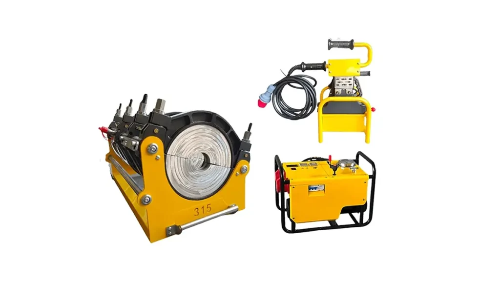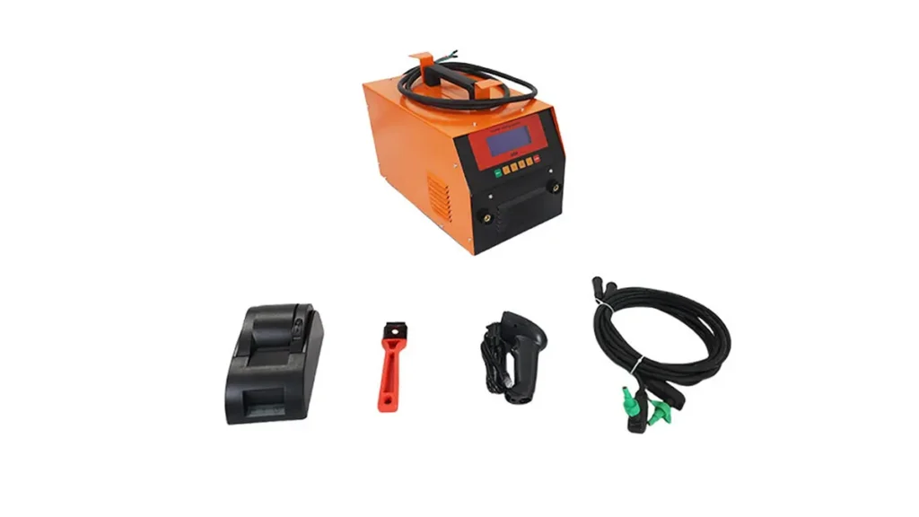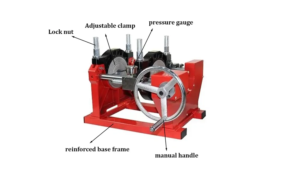
Electrofusion welding machines rely on precise control electronics to deliver consistent, high-quality joints in HDPE piping systems. When the control system encounters electromagnetic interference (EMI), radio-frequency interference (RFI), or transient surges, weld parameters can drift, cycles abort, or equipment may fail — all of which undermine field productivity and pipeline integrity. This guide outlines practical anti-interference measures to improve control system stability and ensure reliable electrofusion welding performance.
Why electrofusion control systems are vulnerable
Control units for electrofusion units contain sensitive voltage and current measurement circuits, microcontrollers, and communication ports (USB, RS485, CAN). These components can be disrupted by nearby switching equipment, long power cables, mobile radios, or even static buildup during dry weather. Uncontrolled interference can lead to incorrect heating times, incomplete fusions, and frequent maintenance stops.
Common sources of interference
-
Power supply noise: Poorly filtered mains, switching transients from generators or pumps.
-
Nearby heavy equipment: Excavators, diesel generators, and welding rigs can radiate EMI.
-
Cabling issues: Long unshielded signal/power runs and improper grounding loops amplify disturbances.
-
Environmental factors: Moisture, dust, and static charge build-up around the fusion joint and connectors.
Effective hardware anti-interference measures
Shielding – Use braided shielded cables for all sensor and communication lines. Connect shields to a single-point ground at the control panel to prevent ground loops.
Filtering – Fit EMI/RFI line filters on AC mains and DC supply lines. Add common-mode chokes and ferrite beads on signal cables to suppress high-frequency noise.
Surge protection – Install surge arrestors and transient voltage suppressors on power inputs and external ports to guard against lightning-induced and switching transients.
Separation & routing – Route power and signal cables separately; avoid parallel runs. Keep sensitive sensor wiring away from contactors, motors, and high-current conductors.
Grounding & bonding – Use a low-impedance ground system. Ensure machine chassis, heating plates, and frames are bonded to the same equipotential point.
Practical software and control-level strategies
Signal conditioning: Employ hardware ADC filtering, digital averaging, and hysteresis in control logic to reject short disturbances without losing responsiveness.
Watchdog and fault logging: Enable watchdog timers and persistent fault logs so the control system can recover safely after a transient and technicians can trace recurring interference patterns.
Communications robustness: Use error-checked protocols (CRC) and retransmission logic for RS485/CAN links; consider optical isolation for critical ports.
Quick-reference table: Measures vs. expected improvement
| Measure | Primary Benefit | Typical Impact |
|---|---|---|
| Shielded cabling + single-point ground | Reduces conducted/radiated EMI | High |
| Mains filters & surge arrestors | Protects supply rails from spikes | High |
| Ferrite beads & chokes on sensors | Attenuates HF noise on lines | Medium |
| Software debouncing & CRC checks | Improves resilience to transient glitches | Medium |
| Periodic EMI testing & maintenance | Prevents gradual degradation | High |

Installation & grounding best practices (field tips)
Position the control cabinet on non-conductive mounts where feasible, and fasten grounding conductors with star washers for low contact resistance. Keep earth stakes short and thick, and use multiple ground rods bonded together when working in sandy or rocky soils. If the jobsite uses portable generators, add isolation transformers and filter modules between the generator and the electrofusion machine.
Testing, maintenance & commissioning checklist
-
Verify shield continuity and single-point grounding before first use.
-
Run a no-load EMI check with a handheld spectrum analyzer or EMI meter near control electronics.
-
Confirm power rail stability under load and inspect surge arrester operation.
-
Schedule quarterly inspections of cable routing, connectors, and sensor terminations.
When to involve specialists
If intermittent weld failures persist after implementing standard measures, consult an electrical engineer or EMI specialist for site-specific diagnostics. Advanced solutions can include dedicated grounding grids, Faraday enclosures for control panels, or custom isolation transformers sized for long-duration fusion cycles.
Company & support
JQ-Fusion provides electrofusion and butt-fusion welding equipment with robust control architectures designed for demanding infrastructure projects; visit https://jq-fusionwelding.com/ for product specifications and service support.