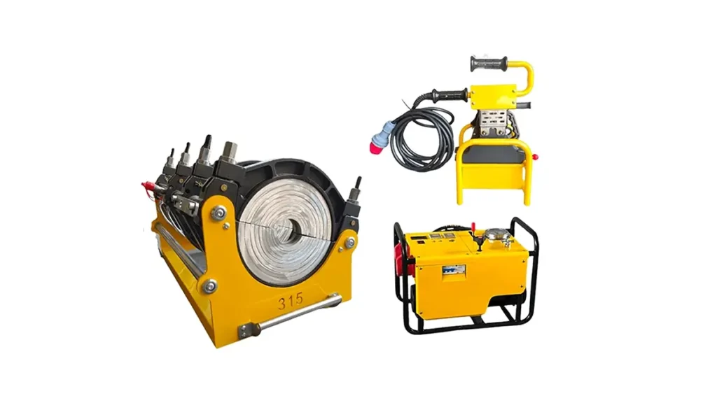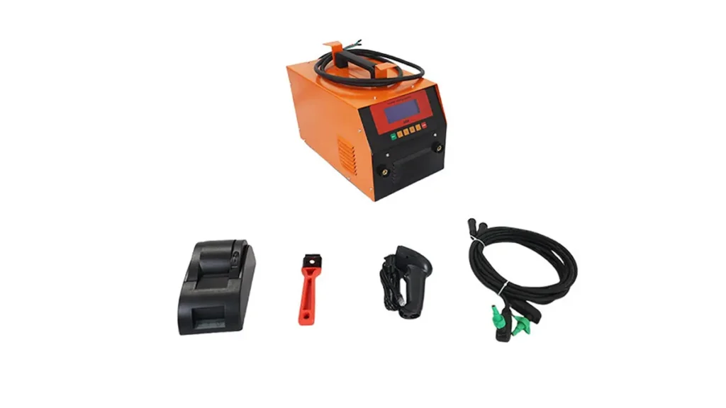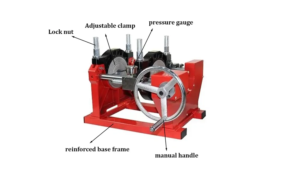
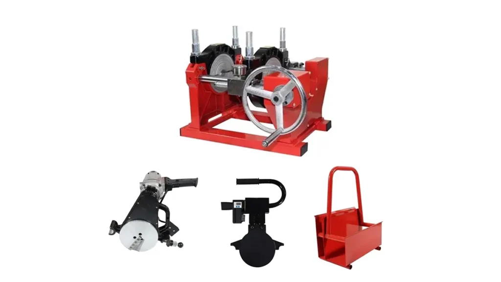
Getting the poly pipe fusion machine pressure settings right is one of the most critical steps in creating leak-free, durable HDPE pipe joints. Whether you are operating a manual, hydraulic, or CNC automatic machine, applying the correct interfacial pressure during the heating and fusion stages directly determines the integrity of the weld. Too little pressure results in poor mixing and weak bonds; too much pressure can squeeze out all the molten material, causing cold joints. This guide explores the essential parameters, standard calculations, and best practices for achieving perfect pipe joints every time.
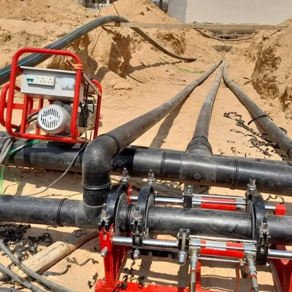
Understanding Interfacial Pressure in Pipe Fusion
In butt fusion welding, the term “pressure” does not simply mean the hydraulic gauge reading. The most critical variable is the interfacial pressure, which is the force per unit area acting on the pipe ends being joined. Standards established by ISO 21307 butt fusion procedures specify that for PE materials, the interfacial pressure should typically be maintained at 0.15 MPa (1.5 bar) during the heating soak phase and 0.15 MPa during the fusion joining phase. To translate this into your machine’s gauge pressure, you must account for factors like pipe diameter, wall thickness, and the machine’s drag resistance.
How to Calculate Correct Drag Pressure
Before setting the final gauge pressure, you must determine the drag pressure (also known as the friction loss) of your specific machine. Hydraulic cylinders and carriage assemblies have internal resistance that must be overcome before any force is transmitted to the pipe faces. To measure this, operate your hydraulic butt fusion machine with the pipes clamped but not touching the facing tool. Slowly extend the cylinder and note the pressure gauge reading when the carriage just begins to move. This is your drag pressure reference point, a value that must be added to the theoretical fusion pressure.
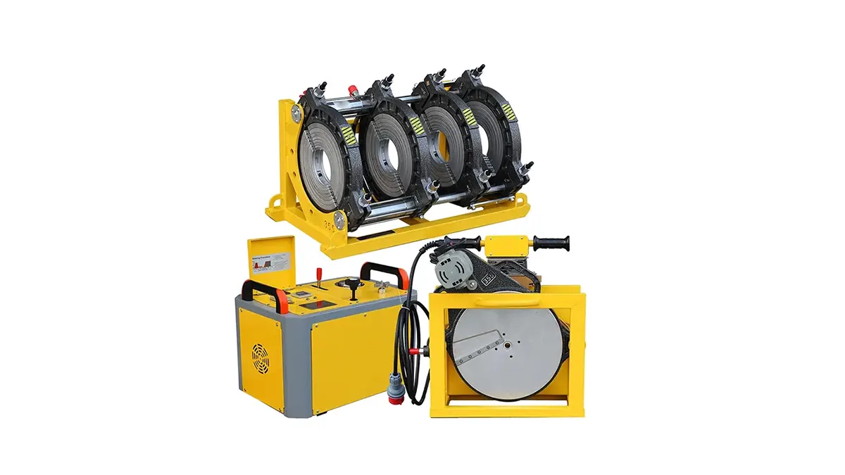
Poly Pipe Fusion Machine Pressure Settings by Diameter
The following table provides a general reference for poly pipe fusion machine pressure settings based on standard dimension ratio (SDR) 11 and SDR 17 pipes. Always verify calculations with the specific data logger or manual for your PE100 or PE4710 material, referencing ASTM F2620 heat fusion guidelines.
| Pipe Diameter (mm) | SDR Rating | Approx. Gauge Pressure Low (bar) | Approx. Gauge Pressure High (bar) |
|---|---|---|---|
| 63 – 110 | SDR 11 | 3 – 8 | 10 – 20 |
| 160 – 250 | SDR 11 | 15 – 30 | 40 – 60 |
| 315 – 500 | SDR 17 | 30 – 60 | 80 – 120 |
| 630 – 1200 | SDR 17 | 60 – 120 | 140 – 220 |
| 1400 – 2250 | SDR 17/26 | 100 – 180 | 200 – 350 |
Note: These values include an estimated drag resistance. Always add your specific machine’s drag to the net fusion pressure calculated for the pipe area.
Manual vs. CNC Automatic Machine Pressure Control
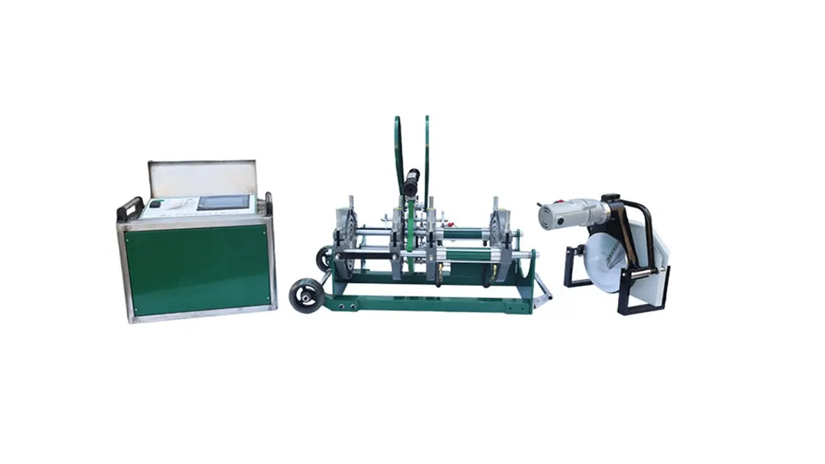
When using a manual butt fusion machine, the operator manually sets and maintains the pressure via a lever or screw mechanism. In these systems, consistency depends heavily on operator skill. It is vital to lock the carriage or maintain steady force during the soak cycle. In contrast, modern CNC automatic butt fusion machines use servo-controlled hydraulic pumps. These units automatically adjust the poly pipe fusion machine pressure settings in real time, compensating for temperature variations and drag, ensuring strict adherence to the PE butt fusion equipment standard without manual intervention.
Common Mistakes in Pressure Adjustment
- Ignoring Drag Pressure: Failing to compensate for the machine’s sliding resistance is the most common error. It leads to insufficient interfacial pressure and a weak weld core.
- Misreading the Cylinder Area Ratio: If the machine has a differential cylinder, the gauge pressure does not equal the actual output force. Always check the machine’s calibration chart.
- Cold Pipe Ends: High pressure cannot compensate for a cold heater plate. The initial bead-up phase must be performed under controlled pressure, not brute force.
- Pressure Spikes During Cooling: Moving the pipe or unclamping too early disrupts the grain structure; hold the static pressure or locked position as specified in the PPI butt fusion procedure.
Standard Fusion Cycle Breakdown
For a dual low-pressure profile machine, the cycle typically follows this sequence. Adhering to these stages is essential for compliance with international project specifications:
1. Bead Up
Apply 0.15 MPa ± 0.01 MPa interfacial pressure to form a uniform melt bead around the circumference.
2. Heat Soak
Reduce to drag-only pressure (near zero gauge) while the material absorbs heat through its thickness.
3. Heater Removal
Separate pipes, retract the heater plate, and close the carriage within the maximum dwell time (typically 5-8 seconds).
4. Fusion & Cooling
Re-apply 0.15 MPa interfacial pressure gradually. Maintain clamping until the joint cools below 60°C.
Calibrating Your Hydraulic Fusion Machine
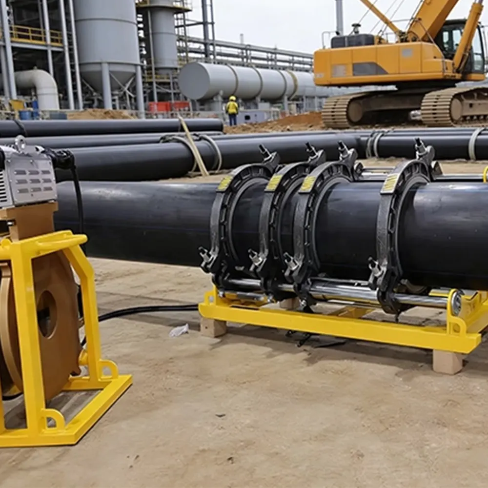
To ensure your poly pipe fusion machine pressure settings are accurate, regular calibration with a load cell is recommended. Over time, hydraulic seals wear, and gauge needles drift. A machine that displays 50 bar on the gauge might actually be delivering a significantly different force. JQ-Fusion, a professional manufacturer specializing in HDPE pipe welding machines, integrates precision hydraulic control valves in its equipment to minimize pressure fluctuations. For the best results, log the actual interfacial pressure during each weld using a data logger, a requirement increasingly demanded by standards such as heat fusion operator qualification programs.
Tools and Accessories for Accurate Pressure Control
Achieving the perfect bead-up pressure also relies on ancillary tools. The main features to check include:
- Calibrated Digital Gauges: Replace analog dials with digital transmitters for better resolution.
- Data Loggers: Record temperature and pressure traces for quality assurance records, linking to PE fusion traceability coding.
- Trimmer Blade Condition: Clean, sharp blades reduce the need for excessive facing pressure and ensure square pipe ends.
- Heater Plate Surface Temperature: Ensure uniform heat (typically 200-230°C). Cold spots lead operators to over-pressurize to force a false bead.
Final Thoughts on Perfect Pipe Joints
Mastering poly pipe fusion machine pressure settings is a balance between physics, machine condition, and operator training. The exact gauge number varies for every single machine on-site, which is why copying values from a colleague without calculating your own drag is risky. Always reference the pipe manufacturer’s melt flow specifications and the welding standard applicable to your project, whether it covers gas, water, or industrial applications. By consistently applying the correct interfacial force, you ensure the dual-bead rollback appearance and the molecular entanglement required for a lifetime of reliable service.