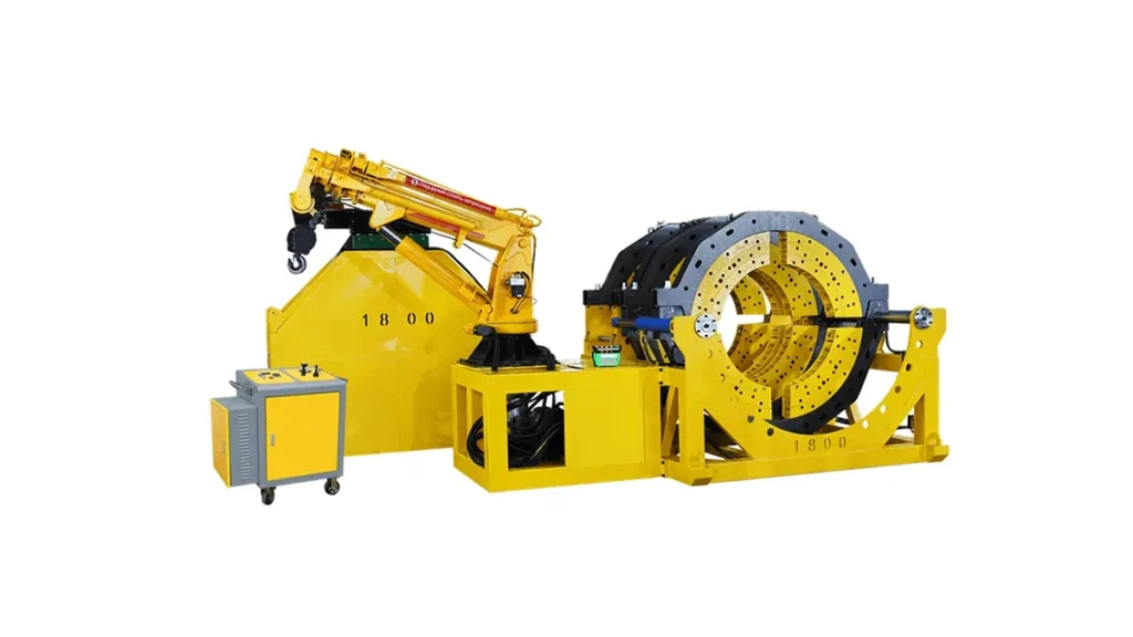
Understanding pipe fusion machine welding time is critical for project managers, contractors, and engineers working with HDPE piping systems. Whether you are installing water mains, gas distribution lines, or industrial slurry pipelines, accurate time estimation keeps your schedule on track and helps control labor costs. In this guide, we break down the factors that influence welding duration, provide typical cycle times by machine type, and offer practical insights to optimize your workflow.
What Determines Pipe Fusion Machine Welding Time?
The total pipe fusion machine welding time is not a single fixed number. It depends on a combination of variables that interact during every joint. Understanding these elements allows you to build realistic project timelines and avoid costly downtime.
- Pipe diameter and wall thickness (SDR rating) – Larger, thicker pipes require longer heating, soaking, and cooling phases. A 315mm SDR11 pipe takes significantly more time than a 110mm SDR17 pipe.
- Machine type and automation level – Manual, hydraulic, and CNC automatic butt fusion machines each have different speed characteristics. CNC systems optimize cycle phases, while manual machines depend heavily on operator efficiency.
- Ambient temperature and weather conditions – Cold environments slow heat absorption, while windy conditions can cool the heating plate unevenly, extending the soak time.
- Fusion pressure and drag resistance – Properly calibrated machines with well-maintained clamp inserts reduce drag and ensure consistent bead formation without unnecessary delays.
- Operator skill and preparation – Experienced technicians who follow ISO 21307 butt fusion procedures complete joints faster while maintaining quality.
Typical Welding Cycle Breakdown: A Step-by-Step Timeline
Every butt fusion joint follows the same fundamental phases defined by international standards. Below is a table illustrating the relative time distribution for a mid-range HDPE pipe using a hydraulic butt fusion machine. Actual minutes vary by diameter, but the proportional allocation remains consistent.
| Fusion Phase | Description | Approximate Time Allocation |
|---|---|---|
| Pipe Clamping & Facing | Aligning pipe ends, securing clamps, and trimming with the facing tool until a continuous shaving emerges from both sides | 10-15% of total cycle |
| Heating Plate Insertion & Bead-up | Pressing pipe ends against the heated plate under specified pressure to form an initial melt bead | 15-20% of total cycle |
| Soak Time (Heat Penetration) | Reducing pressure to near zero while the pipe ends absorb heat through the wall thickness | 25-35% of total cycle |
| Plate Removal & Fusion | Quickly withdrawing the heating plate and bringing molten pipe ends together under fusion pressure | 5-8% of total cycle |
| Cooling Under Pressure | Holding the joint under pressure until the material solidifies sufficiently to be removed from the clamps | 30-40% of total cycle |
Cooling time typically dominates the overall pipe fusion machine welding time. Rushing this phase compromises joint integrity and leads to premature field failures.
Welding Time Estimates by Pipe Diameter and Machine Type
The table below provides realistic cycle time ranges for single joints using properly maintained equipment under moderate ambient conditions (around 20°C / 68°F). These estimates align with the PPI butt fusion procedure guidelines.
| Pipe Diameter (mm) | SDR Rating | Manual Machine (min) | Hydraulic Machine (min) | CNC Automatic Machine (min) |
|---|---|---|---|---|
| 63 – 110 | SDR11 – SDR17 | 8 – 15 | 6 – 12 | 5 – 10 |
| 160 – 250 | SDR11 – SDR17 | 15 – 28 | 12 – 22 | 10 – 18 |
| 315 – 450 | SDR11 – SDR17 | 30 – 50 | 25 – 40 | 20 – 35 |
| 500 – 800 | SDR11 – SDR17 | — | 45 – 75 | 40 – 65 |
| 1000 – 1600 | SDR11 – SDR17 | — | 80 – 130 | 70 – 110 |
| 1800 – 2250 | SDR11 – SDR17 | — | 140 – 220 | 120 – 190 |
Note: Manual machines above 315mm are impractical for field use. Hydraulic and CNC systems dominate large-diameter applications.
Manual vs. Hydraulic vs. CNC Automatic: Speed Comparison
Machine automation directly impacts both cycle consistency and total elapsed time per joint. Here is how each category compares in terms of pipe fusion machine welding time efficiency:
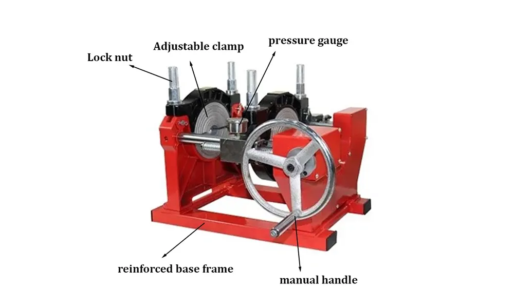
- Manual Butt Fusion Machines – Best suited for small diameters up to 250mm. Operators manually control each phase, so time varies with skill. Typical 110mm joint: 10–15 minutes. See equipment options for manual butt fusion machines.
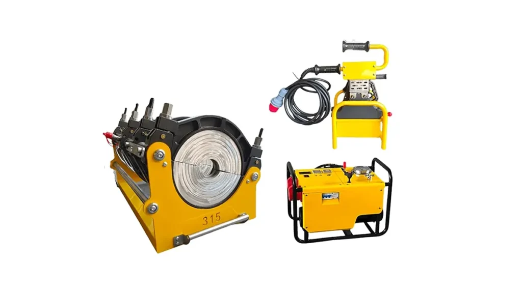
- Hydraulic Butt Fusion Machines – Provide consistent pressure application and faster clamp adjustment. Typical 315mm joint: 25–35 minutes. These are the industry standard for municipal water and gas projects.
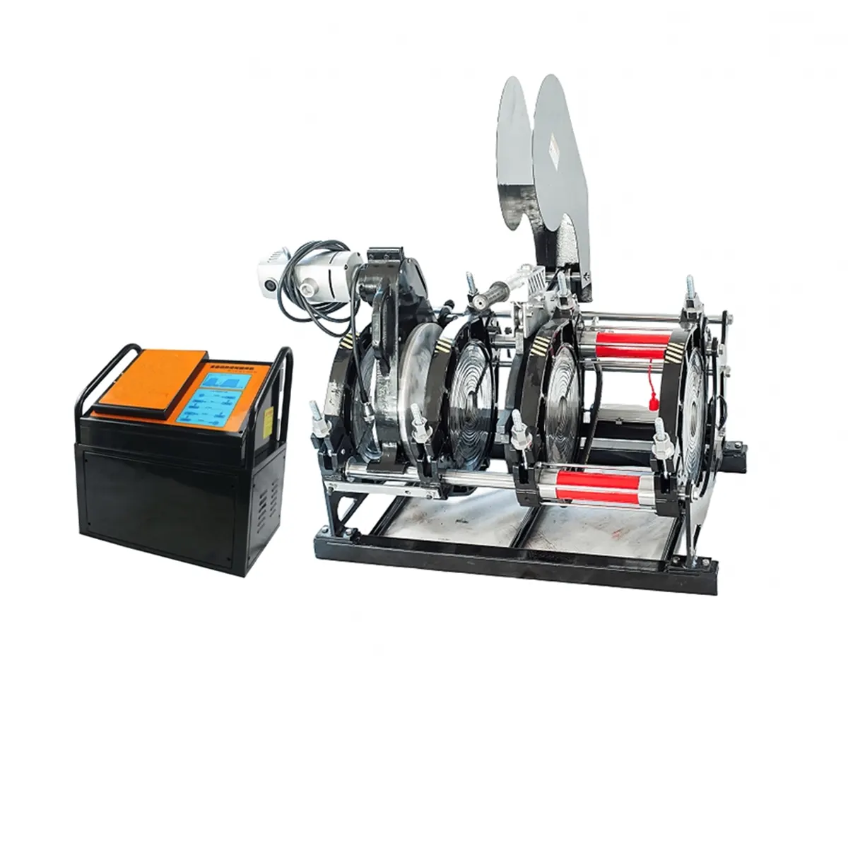
- CNC Automatic Butt Fusion Machines – Pre-programmed parameters eliminate operator guesswork and optimize each phase transition. Typical 315mm joint: 20–28 minutes. The CNC automatic fusion machine also records data for traceability, reducing inspection rework time.
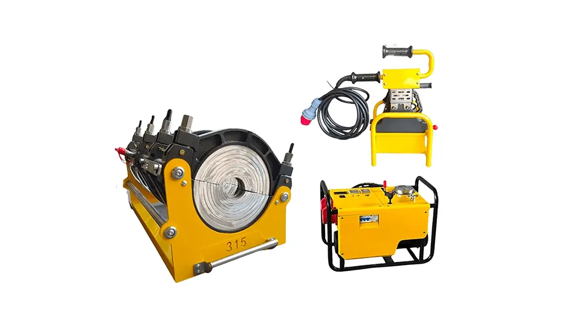
How to Reduce Pipe Fusion Machine Welding Time Without Sacrificing Quality
While you should never rush a fusion cycle, several best practices help you achieve the shortest realistic pipe fusion machine welding time while maintaining joint integrity:
- Pre-heat the heating plate properly – Allow the plate to stabilize at the target temperature (typically 210°C–225°C for PE) before starting. A fluctuating plate extends soak time unpredictably.
- Maintain clean, sharp facing tools – Dull blades increase facing time and produce uneven surfaces that require longer heating to compensate.
- Use calibrated hydraulic systems – Properly set fusion pressure and drag compensation prevent over- or under-beading, which can force rework.
- Shield the work area from wind and precipitation – Temporary shelters significantly reduce heat loss and shorten soak phases in adverse weather.
- Train operators on heat fusion operator qualification programs – Skilled crews complete joints faster and with fewer rejections.
- Choose the correct machine for the pipe range – Undersized equipment struggles with clamp force and heating uniformity, adding unnecessary minutes to every joint.
Real-World Productivity: Joints Per Day Estimates
Project planners often need daily output figures rather than single-joint times. The following scenarios assume an 8-hour shift with one machine and a two-person crew, including setup, alignment, and movement between joints.
| Diameter Range | Machine Type | Estimated Joints Per 8-Hour Shift |
|---|---|---|
| 63mm – 160mm | Manual / Hydraulic | 20 – 35 |
| 200mm – 315mm | Hydraulic / CNC Automatic | 12 – 20 |
| 400mm – 800mm | Hydraulic / CNC Automatic | 6 – 12 |
| 1000mm – 2250mm | Large Hydraulic / CNC | 2 – 5 |
These figures assume continuous operation with minimal downtime. Site logistics, trench conditions, and pipe handling equipment availability often reduce actual daily output by 15–25%.
Common Mistakes That Extend Welding Time
Avoid these frequent errors that unnecessarily prolong pipe fusion machine welding time:
- Skipping daily heating plate surface checks – contaminated plates transfer heat unevenly, forcing operators to extend soak time.
- Incorrect drag pressure measurement – failing to compensate for machine resistance leads to improper bead formation and potential re-fusion.
- Premature clamp release – removing the pipe before adequate cooling causes joint misalignment and scrap.
- Using mismatched insert sizes – oversized or undersized clamp inserts create alignment problems that take extra minutes to correct.
Electrofusion Welding Time Considerations
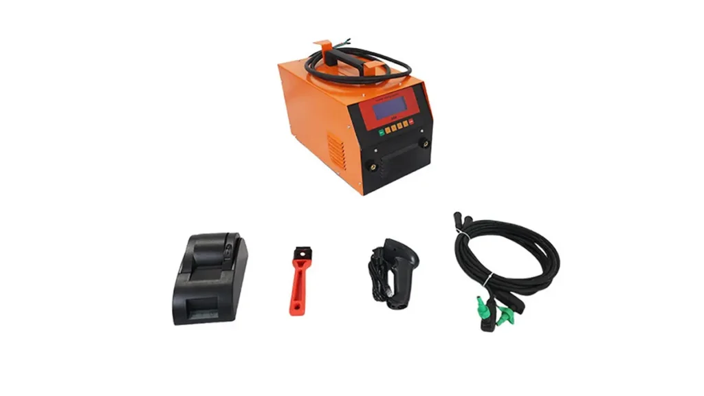
For branch saddles, repairs, and tight-access installations, electrofusion offers an alternative with different time characteristics. A typical electrofusion machine completes a coupling in 2–8 minutes of active fusion time, plus surface preparation and cooling. While individual joint time is shorter than butt fusion for equivalent diameters, the cost per fitting is higher, and scrape-and-clean preparation adds labor minutes.
Why Machine Quality Matters for Consistent Welding Times
Not all fusion equipment delivers the same cycle efficiency. Reliable manufacturers like JQ-Fusion design machines with precision-machined clamp inserts, responsive hydraulic systems, and accurate digital temperature controls. These features ensure that the heating, soaking, and cooling phases proceed according to plan without time-wasting corrections. When evaluating equipment, prioritize the PE butt fusion equipment standard compliance and field-proven durability over initial purchase price.
Planning Your Project Timeline: Key Takeaways
- Estimate pipe fusion machine welding time conservatively, especially for large diameters where cooling dominates.
- Select the appropriate automation level – CNC machines deliver the fastest, most repeatable cycles for critical infrastructure.
- Factor in site conditions, crew experience, and machine setup when calculating daily joint output.
- Always follow manufacturer pressure and temperature settings; deviations do not save time, they create defects.
- Invest in operator training and routine machine maintenance to sustain optimal cycle times over the project lifespan.
By understanding the variables that control pipe fusion machine welding time and choosing the right equipment for your application, you can build accurate schedules, reduce idle labor, and deliver projects on budget. For tailored recommendations on machine selection and cycle time optimization, consult with experienced suppliers who understand both the technical standards and the practical realities of field welding.