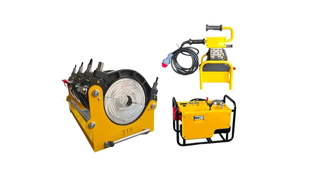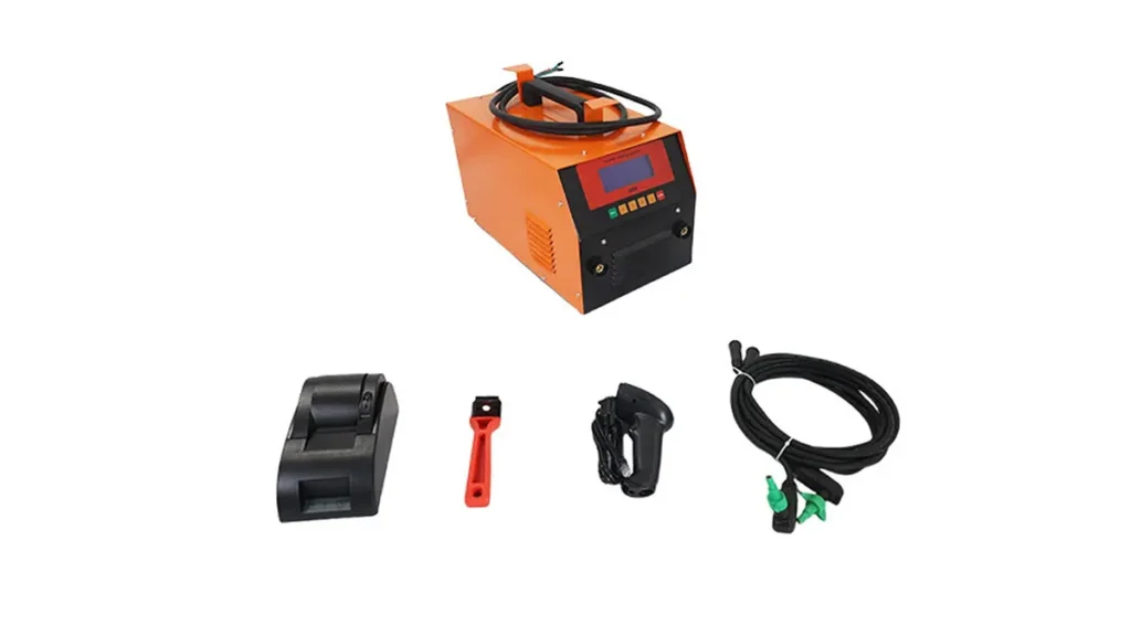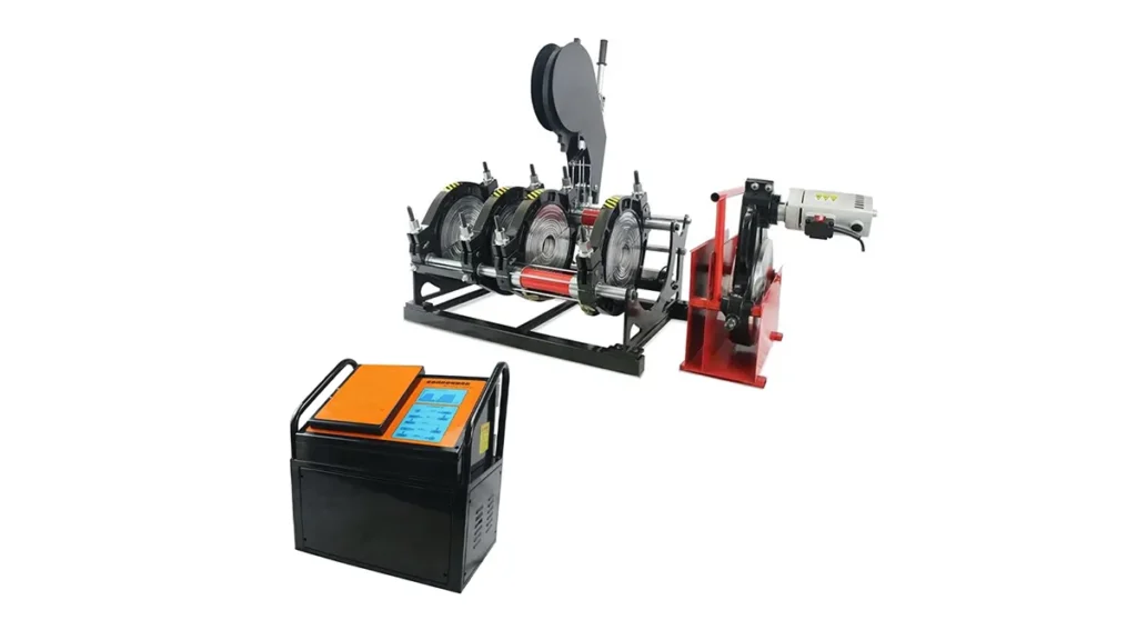
Achieving a precise, leak-free joint relies on mastering one critical variable: HDPE pipe fusion machine pressure. Whether you are operating a manual rig on a municipal water project or a CNC automatic butt fusion machine for gas distribution, applying the correct interfacial force ensures the melted pipe ends mix properly, creating a homogeneous bond that is stronger than the pipe itself. Incorrect pressure settings can lead to cold joints, excessive melt bead flow, or catastrophic field failures, making it essential to understand the science behind force application.
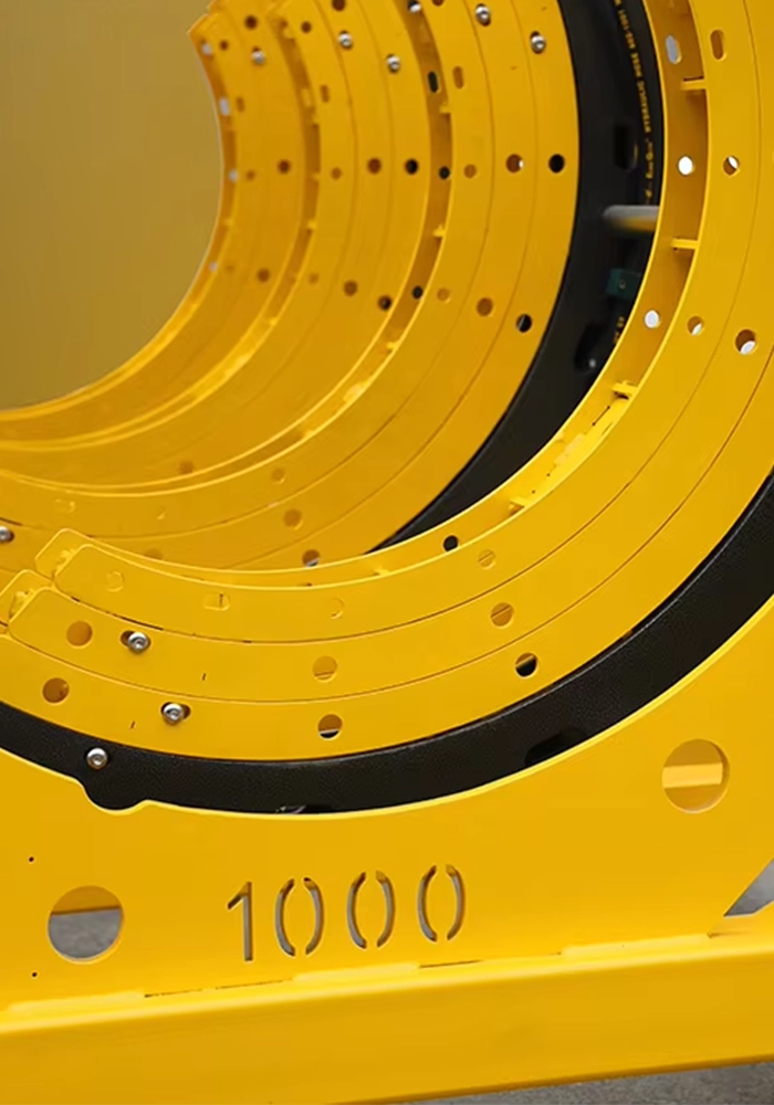
Why Correct Pressure Settings Define Weld Integrity
The primary purpose of controlled HDPE pipe fusion machine pressure is to manage the thermoplastic flow during the heating and cooling stages. During the heating phase, the drag pressure (the force required to move the carriage) must be precisely measured and compensated for. Once the pipe ends are properly soaked at the correct temperature (typically around 220°C/428°F), the fusion pressure is applied. This force squeezes the melted ends together, allowing molecular chains to intertwine across the joint interface. If the pressure is too low, the intermixing is insufficient, resulting in a brittle weld. If it is too high, too much molten material is squeezed out, causing cold slippage and a weakened bead profile.
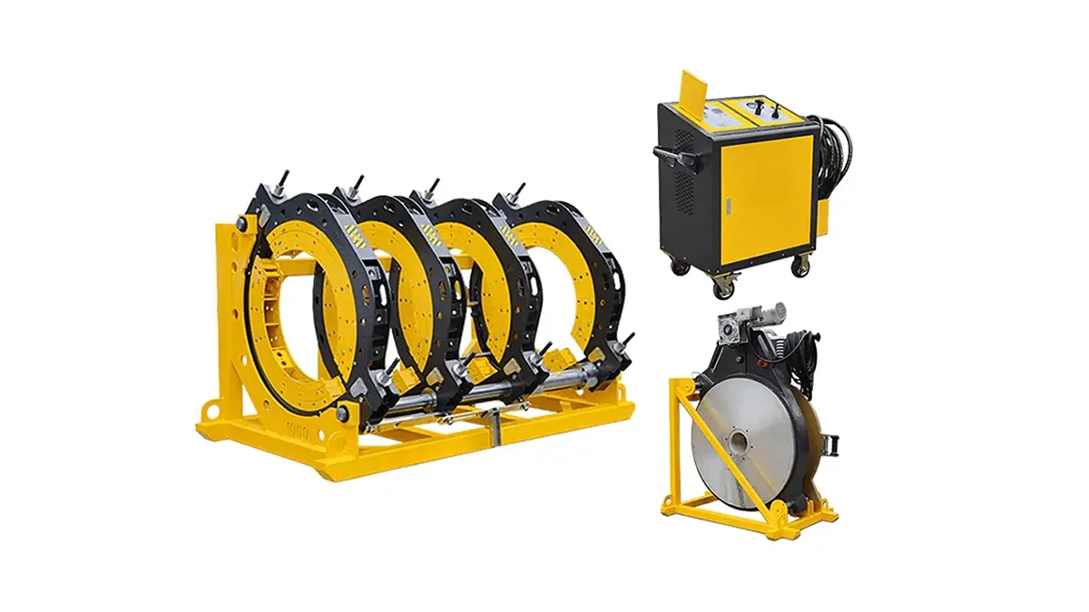
For operators working with high-density polyethylene systems, selecting a reliable hydraulic butt fusion welding machine with accurate pressure regulation is the first step toward compliance with global standards.
Standard Pressure Parameters and Interfacial Force
Most industry standards, including ISO 21307 butt fusion procedures, specify a standard interfacial pressure. The industry benchmark is typically 0.15 N/mm² (or 150 kPa / 21.8 PSI) for PE100 and PE4710 materials. However, this is the interfacial pressure acting on the pipe wall area, not the gauge pressure on your machine. You must calculate the required machine gauge pressure using the following relationship:
| Parameter | Symbol | Standard Value (PE100/PE4710) |
|---|---|---|
| Interfacial Fusion Pressure | Pf | 0.15 N/mm² (21.8 PSI) |
| Drag/Dynamic Pressure | Pdrag | Measured on site (Depends on machine friction) |
| Required Gauge Pressure | Pgauge | Calculated: Pgauge = (Pf × Pipe Area) / Piston Area + Pdrag |
Recommended Pressure Settings by Pipe Diameter (Hydraulic Machines)
While the exact gauge pressure depends on your specific machine’s hydraulic piston area, the following table provides general guidance for HDPE pipe fusion machine pressure ranges observed on standard hydraulic units welding SDR 11 pipes. Always refer to the manufacturer’s manual for your specific hydraulic pipe welding equipment.
| Pipe OD (mm) | SDR Rating | Approx. Fusion Force (kN) | Typical Gauge Pressure (Bar/PSI)* |
|---|---|---|---|
| 110 mm | SDR 11 | ~4.7 kN | Low / 10-20 Bar |
| 250 mm | SDR 11 | ~24.5 kN | 30-50 Bar |
| 500 mm | SDR 11 | ~98 kN | 60-90 Bar |
| 800 mm | SDR 11 | ~251 kN | 100-140 Bar |
| 1200 mm | SDR 11 | ~565 kN | 150-200+ Bar |
*Note: Gauge pressure is machine-specific. These values are estimates for mid-range hydraulic cylinder diameters.
Mastering Drag Pressure Measurement
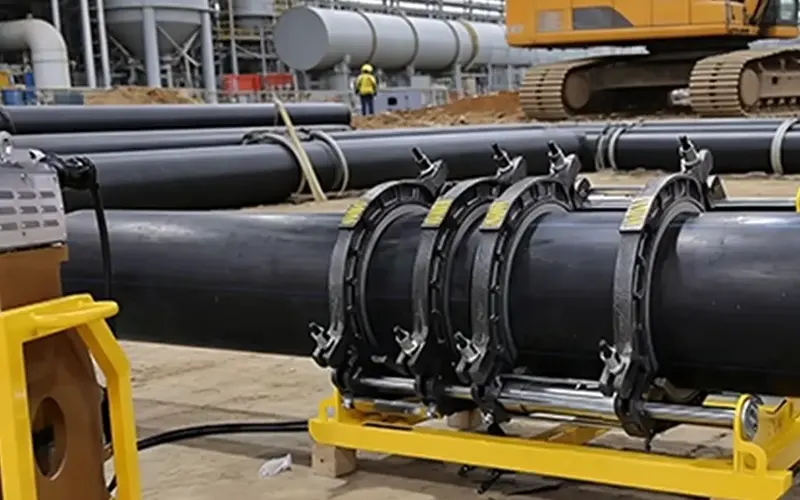
One of the most overlooked aspects of setting HDPE pipe fusion machine pressure is the correct determination of drag. Drag pressure is the additional force needed to overcome the mechanical resistance of the machine’s carriage. Without compensating for drag, your actual interfacial fusion pressure will be insufficient, leading to a cold joint failure. The best practice involves moving the carriage slowly using the hydraulic lever while monitoring the pressure gauge. The pressure at which the carriage just begins to move steadily is your drag pressure. This value must be added to the calculated theoretical fusion pressure.
Manual Machines: Manual Torque and Pressure
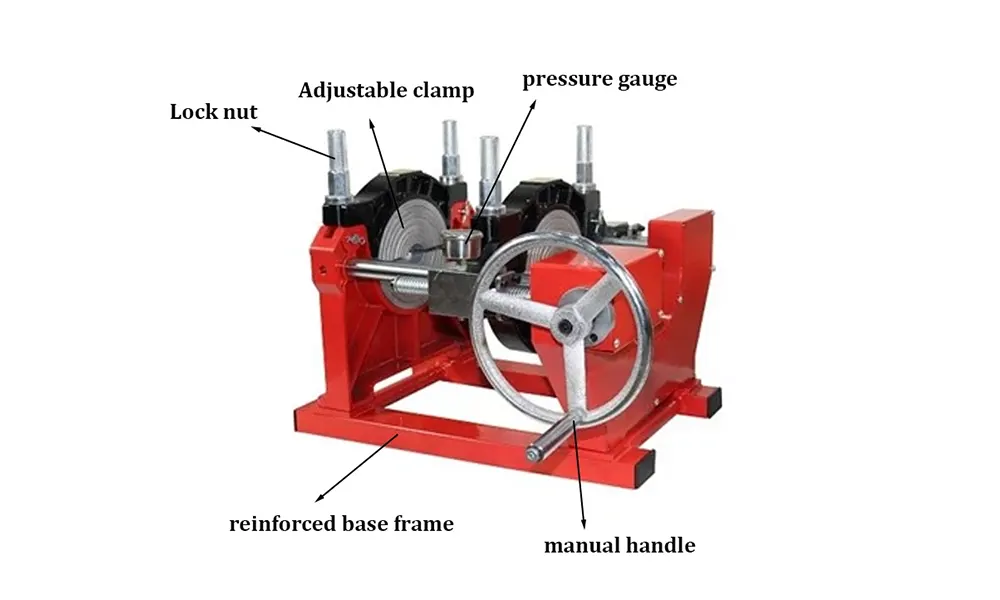
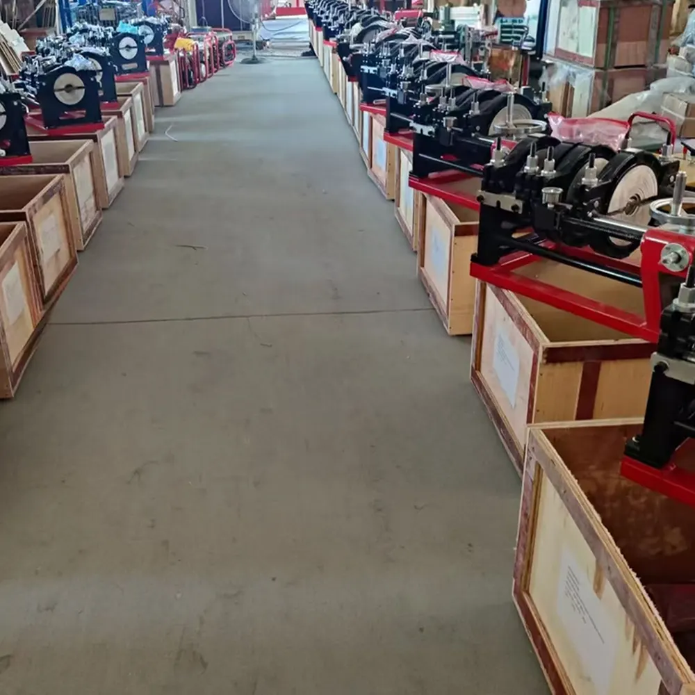
For manual manual butt fusion welding machines, pressure is often applied via a screw mechanism or a basic lever. While these systems may not have a gauge, the principle of interfacial pressure remains. Operators must rely on the visual formation of the melt bead to gauge correct pressure. The bead should form uniformly around the circumference. If you are pinching the pipe without a visible melt, the pressure is too high relative to the heat soak.
Automatic Machines: Precision and Traceability
Modern CNC and automatic systems automate force calculation. The operator simply inputs the pipe dimensions and material grade. The machine’s processor calculates the exact HDPE pipe fusion machine pressure required, automatically compensating for drag. These systems, compliant with ASTM F2620 heat fusion standards, often log the actual applied pressure, providing traceability for quality assurance on gas and water infrastructure projects.
Troubleshooting Pressure-Related Weld Defects
Diagnosing visual defects often points directly to pressure mismanagement. Here are common issues linked to HDPE pipe fusion machine pressure settings:
- Insufficient Bead Width or Flat Bead: Indicates low fusion pressure or failure to add drag pressure. The melt did not experience adequate intermolecular diffusion.
- Excessive Melt Bead Rollback (Large “Rolled” Top Bead): Indicates pressure was applied too early before the melt front achieved sufficient depth, squeezing cold material toward the center.
- Uneven Bead Size Around Circumference: Often a result of misalignment, but can also point to uneven pressure distribution due to a faulty hydraulic system or worn clamps.
- Brittle Shear Failure at the Joint: Classic sign of a cold weld caused by fusion pressure being significantly below the required 0.15 N/mm² interfacial force.
Hydraulic System Maintenance for Consistent Pressure
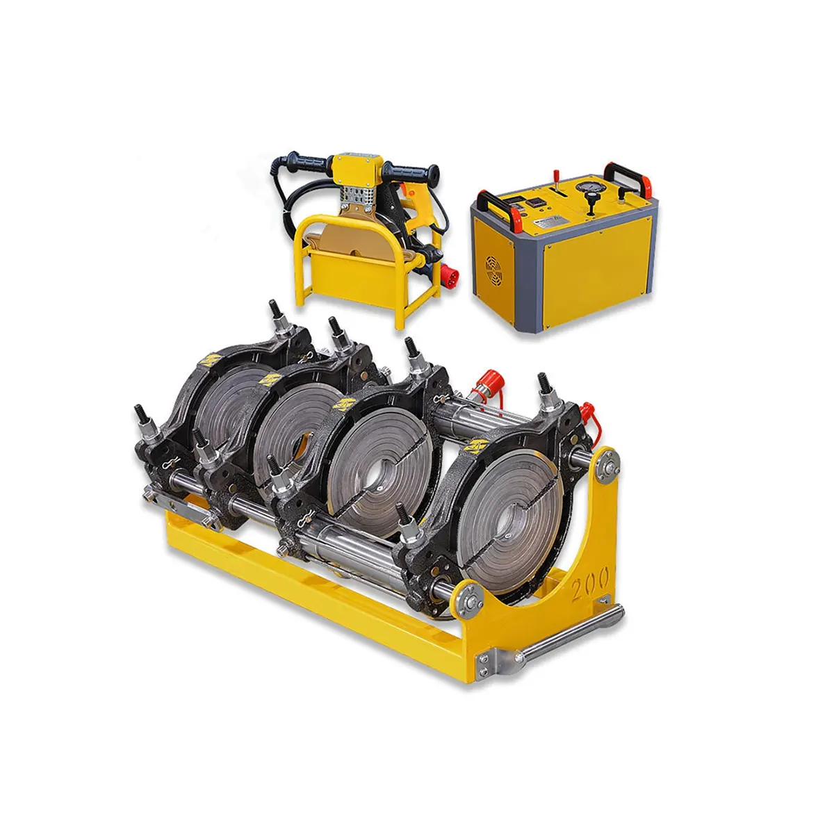
Even the most accurate calculations are useless if the hydraulic power unit fails to deliver stable HDPE pipe fusion machine pressure. Regular maintenance is non-negotiable. Check hydraulic fluid levels and replace hydraulic oil filters according to the manufacturer’s schedule. Air in the hydraulic lines can cause spongy, fluctuating pressure readings. Bleeding the system regularly ensures the gauge reflects the true force being applied. Inspect hoses for any signs of leakage, as a minor drop in hydraulic flow can sabotage a large-diameter weld during the crucial cooling phase. At JQ-Fusion, our hydraulic systems are tested under full load to guarantee steady pressure output.
Best Practices Checklist for Operators
To ensure consistent results and comply with PPI butt fusion procedure guidelines, follow this operational checklist every time you set up your machine:
- Verify the pipe material and SDR rating to determine the exact fusion force requirement.
- Measure the drag pressure with the pipe ends separated before heating begins.
- Ensure the heater plate surface temperature is verified with a contact pyrometer (220°C ± 10°C).
- Calculate the total gauge pressure: Gauge Pressure = Fusion Pressure + Drag Pressure.
- During the “Bead Up” phase, watch for a uniform melt bead forming without applying excessive initial force.
- Monitor the pressure gauge during the cooling cycle to ensure no drift occurs.
- Document the actual applied pressure for joint traceability records.
The Role of Temperature and Environmental Factors
It is vital to remember that HDPE pipe fusion machine pressure does not work in isolation. Ambient temperatures dictate the heat soak time. In cold weather, the melt front develops slower, and there is a temptation to increase pressure to compensate—this must be avoided. Instead, extend the heating cycle per standard protocols (like ISO 21307) while keeping the interfacial pressure constant. Wind shields and thermal blankets are essential accessories during outdoor fusion to prevent uneven cooling, which can create thermal stresses that interact negatively with the fusion pressure profile.
Calculating Pressure for Non-Standard Pipe Dimensions
Field engineers often encounter non-standard wall thicknesses. In these cases, generic pressure tables fail. The formula for the total fusion force (F) remains: F = P_f × A_pipe, where A_pipe is the cross-sectional area of the pipe wall (π × (OD – wall thickness) × wall thickness). Once you determine the required force (F) in Newtons, divide by the machine’s effective piston area to find the gauge pressure. Digital calculators and reference cards are indispensable tools for ensuring quick, error-free setup on a hydraulic butt fusion machines when switching between different pipe schedules.
Frequently Asked Questions About Fusion Pressure
What happens if I use too much pressure when fusing HDPE pipes?
Excessive HDPE pipe fusion machine pressure forces all molten material out of the weld zone, bringing the relatively cold underlying material into contact. This creates a weak “cold slip” plane, visible as a sharp edge on the internal bead. These joints often fail pressure tests immediately or have significantly reduced fatigue life.
How often should I verify the pressure gauge calibration?
Analog pressure gauges should be verified against a calibrated master gauge at least annually, or immediately if the machine has suffered an impact. Inaccurate gauges are a primary source of fixed miscalibration in HDPE pipe fusion machine pressure settings.
Can I use the same pressure for different material grades like PE80 and PE100?
No. PE80 typically uses a slightly lower interfacial pressure (around 0.14 N/mm²) compared to PE100 (0.15 N/mm²). Always consult the resin manufacturer’s specific recommendations to adjust your HDPE pipe fusion machine pressure accordingly.
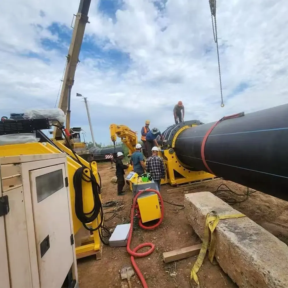
Ultimately, mastering the balance of heat, time, and HDPE pipe fusion machine pressure defines the line between a successful pipeline installation and a potential failure. By adhering strictly to the calculated pressures, maintaining hydraulic equipment, and understanding the mechanical principles at play, operators can deliver robust, code-compliant welds that will last for decades.
Partner with JQ-Fusion for Precision Welding Solutions
JQ-Fusion is a professional manufacturer specializing in HDPE pipe welding machines, providing reliable butt fusion solutions for global infrastructure projects. With years of industry experience, we focus on the development and production of manual, hydraulic, and CNC automatic butt fusion welding machines, covering a wide range of pipe sizes from small to large diameters. Our products are widely used in water supply, gas distribution, mining, and industrial pipeline systems. We are committed to delivering high-quality, durable, and customizable welding equipment to meet diverse project requirements.
For expert guidance on selecting a machine with precise pressure control features, contact our support team today or explore our full product catalog.