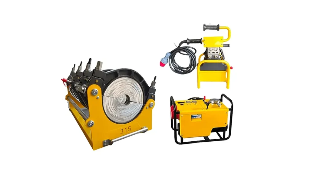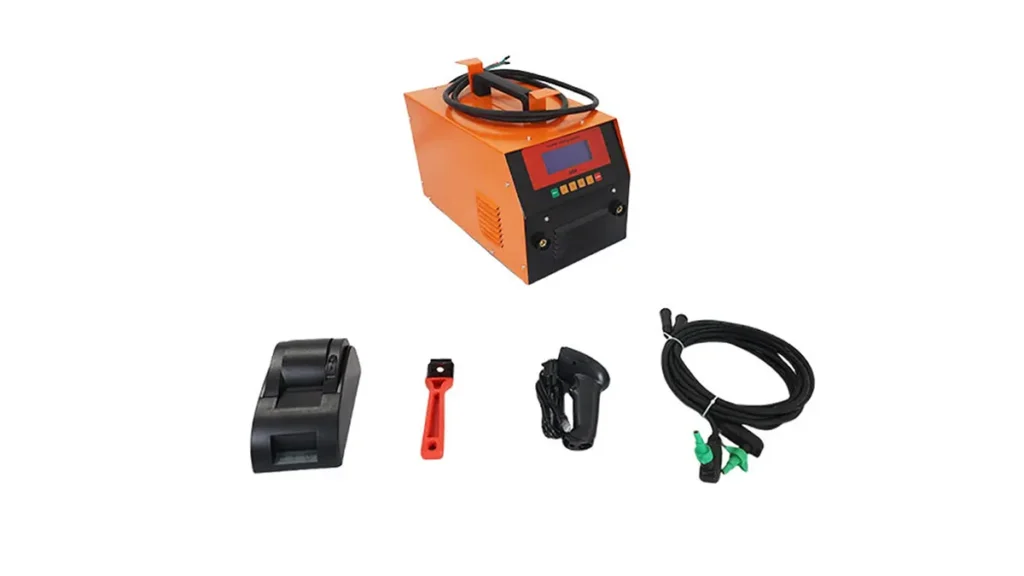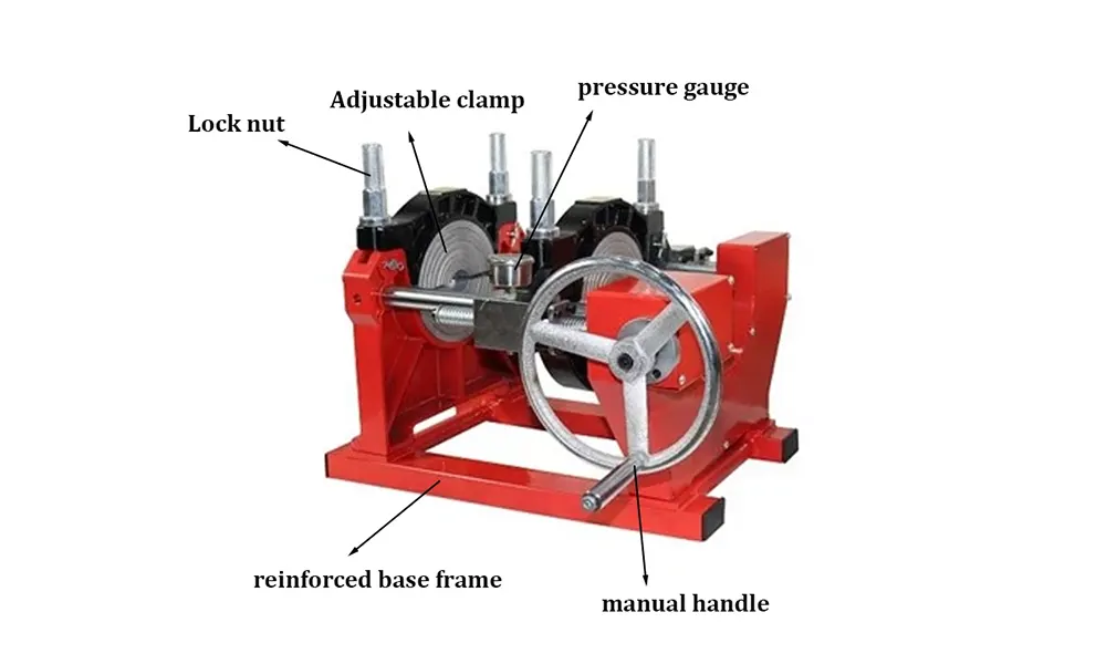
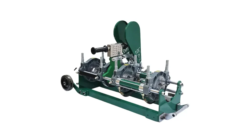
Electric fusion welder control module failures can bring HDPE pipe welding jobs to a halt. This guide explains the most common causes, clear diagnostic steps, and practical fixes so technicians and maintenance teams can restore reliable operation quickly.
Understanding Control Module Failures
Control modules coordinate heating plates, timers, pressure sensors and safety interlocks. When they fail, symptoms range from no-power conditions to intermittent faults during a fusion cycle. Electrical stress, environmental exposure, and user error are frequent contributors.
Top Causes of Control Module Failure
- Power supply problems — voltage spikes, brownouts, or incorrect wiring can damage internal components.
- Moisture and corrosion — condensation or water ingress short circuits PCB traces and connectors.
- Heat stress — repeated thermal cycling degrades solder joints, relays, and capacitors.
- Mechanical vibration — loosens connectors or causes intermittent contacts on field machines.
- Software or firmware glitches — incomplete updates or corrupted memory modules can lock control logic.
Common Symptoms to Watch For
- Unit fails to power on, or display remains blank.
- Heating plate does not reach set temperature or overshoots.
- Intermittent cycle aborts with unexplained error codes.
- Buttons/encoder unresponsive while other functions work.
- Unusual buzzing or burning odors from module area.
Step-by-Step Troubleshooting Guide
Follow these ordered steps to diagnose most control module issues safely and efficiently.
1. Safety First
Always isolate power, wear appropriate PPE, and discharge capacitors before opening the control enclosure.
2. Visual Inspection
Check connectors, wiring harnesses, and PCB for burn marks, bulging capacitors, or corroded pins. Tighten loose terminals and reseat plugs.
3. Verify Power and Grounds
Measure incoming voltage, ground continuity, and any DC rails. Replace blown fuses and confirm proper earth grounding.
4. Isolate Peripherals
Disconnect sensors, heating elements and remote panels one at a time to determine whether an external device is triggering the fault.
5. Review Error Codes and Logs
Consult the control module display or service interface for error codes. Use the OEM manual or built-in diagnostics to map codes to probable causes.
6. Firmware and Calibration
If hardware checks out, confirm firmware version and consider reloading the factory image or performing a safe firmware rollback. Recalibrate sensors and temperature probes.
7. Component-Level Testing
Check relays, fuses, MOSFETs, power supply capacitors and voltage regulators with a multimeter or oscilloscope. Replace failed components with equivalent spec parts.
Quick Diagnostic Checklist
| Symptom | Likely Cause | First Action |
|---|---|---|
| No power / blank screen | Blown fuse, bad PSU, connector loose | Check fuses, verify input voltage, reseat connectors |
| Overtemperature or thermostat errors | Faulty probe, bad calibration | Swap temperature probe, run calibration |
| Intermittent shutdowns | Loose wiring, thermal cycling, failing cap | Inspect connectors, measure capacitors, heat-test board |
| Error codes after firmware update | Corrupted firmware / incompatible build | Rollback or reflash firmware using OEM image |
Repair vs. Replace: Making the Call
If the issue is a single replaceable component (fuse, relay, capacitor, connector) and the PCB shows no extensive damage, repair is cost-effective. Replace the entire control module if PCB traces are burned, multiple surface-mount parts are failing, or the module is obsolete and parts are unavailable.
Preventive Measures to Reduce Future Failures
- Install surge protection and stable power supplies on job sites.
- Keep control enclosures sealed and use desiccant packs in humid climates.
- Schedule routine inspections for loose connectors and corrosion.
- Document firmware versions and only apply tested updates.
- Train operators on correct startup/shutdown sequences to avoid thermal shock.
When to Contact Professional Service
Contact factory-authorized service if you encounter persistent error codes after basic checks, visible PCB burn damage, or if module firmware recovery fails. For replacement modules and calibrated firmware images, reach out to the original equipment manufacturer or certified technicians.
FAQ
Q: Can I run diagnostics without disconnecting the heating plate?
A: It’s safer to isolate high-current peripherals first. Use documented diagnostic modes when available.
Q: How long do control modules typically last?
A: With good preventive care, modules can last many years; harsh environments shorten lifespan.
Manufacturer Note
For replacement parts, firmware images, or certified service for butt fusion and electrofusion machines, contact JQ-Fusion via https://jq-fusionwelding.com/.