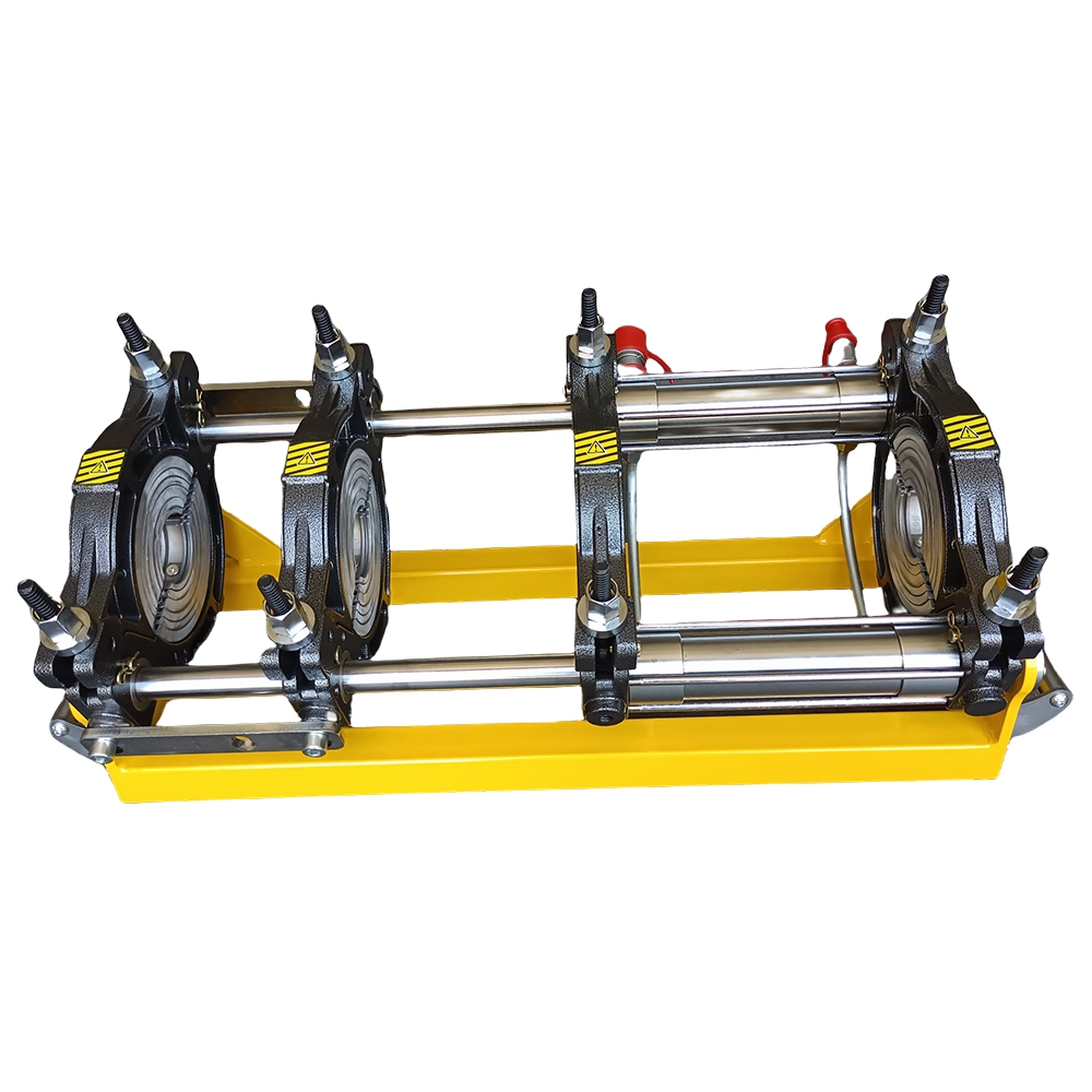
The reliability of an HDPE welding machine electrical system directly determines joint quality and jobsite productivity. Whether you operate a manual, hydraulic, or fully automatic butt fusion welding machine, understanding the electrical architecture, wiring logic, and maintenance requirements helps prevent costly downtime and ensures consistent welds that meet PE butt fusion equipment standard specifications.
Core Electrical Components in HDPE Fusion Machines
Every HDPE pipe welding machine relies on a set of essential electrical components that work together to control heating, movement, and data logging. Below are the primary elements found across most modern machines, from compact manual butt fusion models to large-diameter hydraulic butt fusion welding machines.
Heater Plate Control Circuit
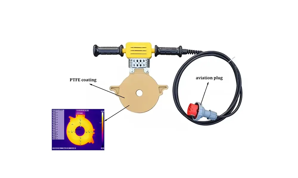
The heater plate is the heart of the fusion process, and its electrical circuit deserves special attention. A precision digital temperature controller maintains the non-stick PTFE-coated heating surface at the required setpoint, typically between 200°C and 230°C (392°F to 446°F) depending on pipe material and ISO 21307 butt fusion procedures. Key circuit elements include:
- Solid-state relay (SSR) – provides fast, silent switching for heater elements without mechanical wear
- Thermocouple or RTD sensor – feeds real-time temperature data back to the controller with ±1°C accuracy
- Over-temperature protection – a secondary thermal cutoff switch that prevents runaway heating if the primary controller fails
- Power indicator lamps – visual confirmation that heating elements are energized
Hydraulic Power Unit Electrical Interface
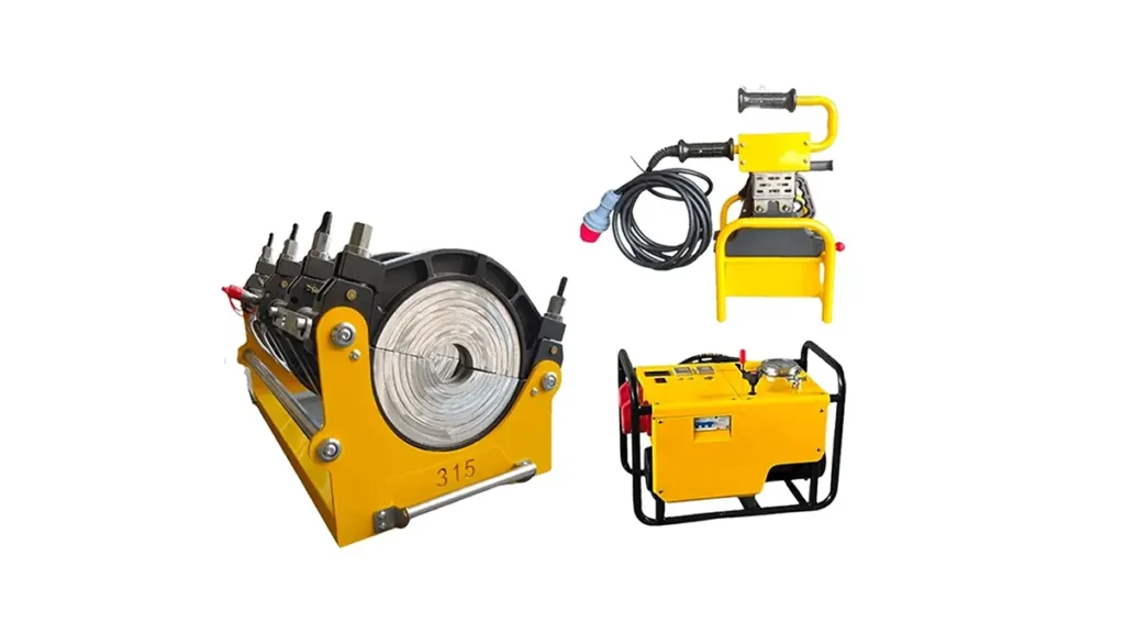
On hydraulic HDPE welding machines, the electrical system must interface seamlessly with the hydraulic power pack. This involves solenoid-operated directional control valves that govern cylinder movement during the critical fusion stages. The electrical panel typically includes push-button stations for manual control and, on advanced models, a programmable logic controller (PLC) that automates the entire drag pressure, heat soak, heater removal, and fusion pressure sequence according to pre-set parameters.
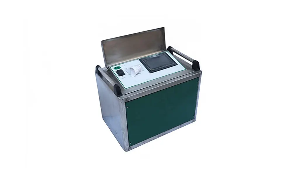
Data Logging and Display Units
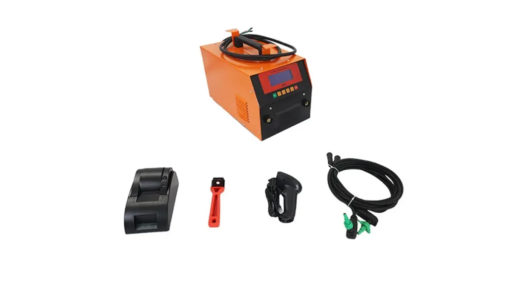
Modern CNC automatic butt fusion welding machines are equipped with onboard computers that record every parameter during the weld cycle. These systems log temperature, pressure, time, and pipe dimensions, generating traceability reports that align with ASTM F2620 heat fusion requirements. The electrical architecture includes a dedicated power supply for the data logger, backup battery for memory retention, and a communication port (USB/Ethernet) for report transfer.
Wiring Layout and Connection Best Practices
Proper wiring is the backbone of a dependable HDPE welding machine electrical system. Field conditions on pipeline projects are often harsh — dust, moisture, vibration, and extreme temperatures all take a toll. The table below summarizes the key wiring zones and recommended practices.
| Wiring Zone | Common Issues | Design Recommendation |
|---|---|---|
| Main power input | Loose terminals, voltage drop, phase imbalance | Use IP67-rated connectors; torque terminals to spec; install phase monitoring relay |
| Heater plate harness | Insulation breakdown from heat exposure, flex fatigue | High-temperature silicone-insulated cable; strain relief at connection points |
| Control panel low-voltage circuits | Signal interference, ground loops | Shielded multicore cable; separate conduit from high-voltage lines |
| Hydraulic solenoid valves | Coil burnout, connector corrosion | DIN 43650 connectors with integrated flyback diode protection |
| Emergency stop circuit | False triggering, welded contacts | Dual-channel safety relay; regularly test under load |
Electrical Panel Interior Organization
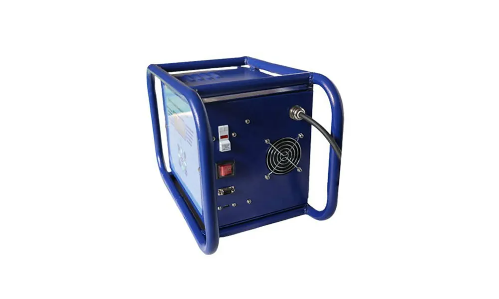
Inside the control cabinet, good housekeeping makes troubleshooting faster and safer. A well-organized panel features clearly labeled terminal blocks, segregated high-voltage and low-voltage compartments, and a clean DIN rail layout for contactors, relays, and circuit breakers. Consistent color coding — for instance, black for AC power, blue for DC control, and green/yellow for protective earth — helps technicians navigate the wiring quickly during field repairs.
Sensors, Switches, and Safety Interlocks
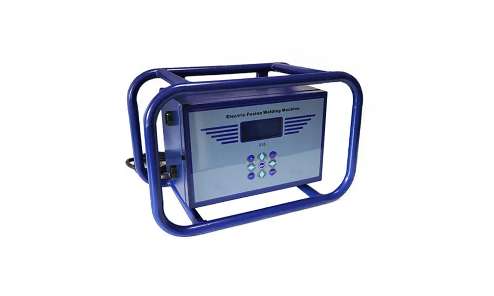
An HDPE welding machine electrical system incorporates multiple sensors and safety devices that protect both the operator and the equipment. Understanding these components helps in diagnosing faults before a minor issue escalates into a major failure.
- Limit switches – detect carriage end-of-travel positions, preventing mechanical overrun that could damage the frame or clamps
- Pressure transducers – convert hydraulic pressure to an electrical signal (typically 4-20 mA) for real-time monitoring and recording; critical for verifying that fusion pressure matches the pipe manufacturer’s specification
- Emergency stop mushroom button – instantly cuts power to all hazardous motions; connected through a safety relay that requires manual reset after activation
- Door interlock switches – on enclosed machines, these prevent heater plate movement while the safety guard is open
- Ground fault detection – continuously monitors leakage current to the machine frame, tripping the main breaker if a fault develops
Common Electrical Faults and Diagnostic Steps
Even the most robust equipment encounters electrical issues in demanding field environments. The following list covers the most frequently reported faults on butt fusion job sites, along with systematic diagnostic approaches that follow guidance from PPI technical guidance.
Symptom: Heater Plate Not Reaching Temperature
- Verify incoming voltage at the machine input terminals — a drop below 10% of rated voltage significantly reduces heating output
- Check continuity across each heating element; an open circuit indicates a burned-out element that requires replacement
- Inspect the solid-state relay input signal from the temperature controller; a missing DC control signal points to a controller fault
- Measure thermocouple resistance and compare with the sensor’s calibration table; a drifted sensor can cause the controller to shut off prematurely
Symptom: Hydraulic Pump Motor Not Starting
- Confirm the emergency stop is released and all interlock circuits are closed
- Check the motor contactor coil voltage; if the coil is receiving voltage but not pulling in, the contactor itself may be faulty
- Inspect the overload relay — if it has tripped, investigate the cause before resetting (locked rotor, excessive load, or phase loss)
- For single-phase motors, test the start capacitor; a failed capacitor is a common reason for motor humming without rotation
Symptom: Erratic Data Logger Readings
- Examine sensor cable shielding continuity; breaks in the shield allow electromagnetic interference from nearby power cables to corrupt signals
- Verify the data logger’s backup battery voltage; a low battery can cause memory errors and unexpected system resets
- Check all plug connections for corrosion or loose pins — a high-resistance connection on a pressure transducer circuit will produce fluctuating readings
Preventive Maintenance Schedule for Electrical Systems
A structured maintenance routine extends the life of an HDPE welding machine electrical system and reduces the likelihood of welding defects caused by equipment malfunction. Based on field experience from projects worldwide, we recommend the following inspection intervals.
| Frequency | Task | Tools Required |
|---|---|---|
| Daily | Visual inspection of all cables, connectors, and indicator lights; test emergency stop function | Visual check, E-stop test log |
| Weekly | Torque-check main power terminals and contactor connections; clean ventilation filters on control cabinets | Torque screwdriver, compressed air |
| Monthly | Verify heater plate temperature calibration with an independent surface probe; test ground fault protection | Calibrated surface thermocouple, insulation tester |
| Quarterly | Inspect all internal wiring for heat damage or rodent intrusion; test solenoid valve coil resistance | Multimeter, inspection mirror, flashlight |
| Annually | Full electrical safety test including insulation resistance and protective earth continuity; replace any degraded contactors or relays | Megger tester, replacement components kit |
Upgrading Older Machine Electrical Systems
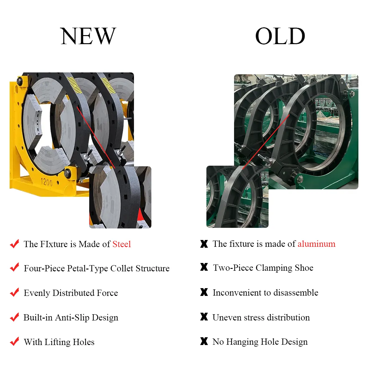
Many contractors continue to operate older hydraulic machines that perform well mechanically but have outdated electrical controls. Retrofitting with a modern PLC-based control system can add data logging, automated fusion cycle control, and remote diagnostics without replacing the entire machine. Common upgrade paths include adding a digital temperature controller with PID auto-tuning for better heating stability, retrofitting a pressure transducer and display for precise hydraulic control, and installing a compact HMI touchscreen to replace banks of selector switches and reduce operator error.
When planning an electrical upgrade, it is wise to specify components that are readily available in your region and to work with a supplier who understands the specific demands of HDPE pipe fusion. As a professional manufacturer, JQ-Fusion supports clients with electrical system specifications, wiring diagrams, and guidance for maintaining peak machine performance. For further assistance with a complete range of butt fusion welding machines or replacement electrical parts, contact our technical team directly.
Explore more electrical system resources:
Technical Support & Wiring Diagrams | Download Product Catalog | Contact Our Electrical Engineering Team