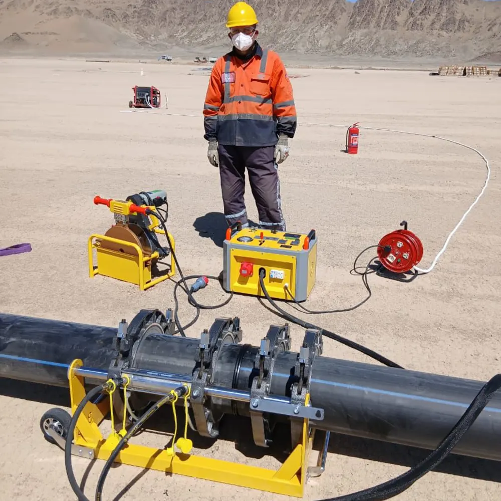
Understanding SDR and Its Impact on HDPE Welding Temperature
The Standard Dimension Ratio (SDR) is a critical factor in determining the correct heat fusion parameters for HDPE pipe. SDR is calculated by dividing the pipe’s outside diameter by its minimum wall thickness. A lower SDR number indicates a thicker pipe wall, which directly influences how heat is absorbed and distributed during the butt fusion welding process. Understanding this relationship is essential for achieving a strong, leak-free joint that meets ISO 21307 butt fusion procedures and other international standards.
While the heater plate surface temperature for HDPE typically falls within a consistent range, the heat soak time, bead-up pressure, and cooling duration vary significantly based on the SDR and pipe diameter. Ignoring these SDR-dependent adjustments is a common cause of cold fusion joints or excessive melt bead formation, both of which compromise pipeline integrity. This guide provides a comprehensive breakdown of welding temperatures and parameters mapped to specific SDR classifications.
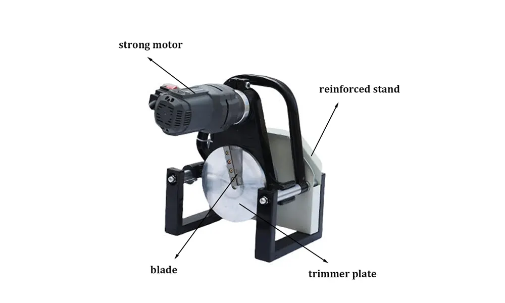
Standard Heater Plate Temperature Range
Before diving into SDR-specific parameters, it is important to establish the baseline heater plate surface temperature. According to ASTM F2620 heat fusion and most pipe manufacturer recommendations, the standard target temperature for HDPE butt fusion is between 400°F and 450°F (204°C and 232°C). The generally accepted optimum is 420°F (215°C). Operating outside this window can lead to joint failure; temperatures that are too low prevent proper molecular mixing, while excessively high temperatures can degrade the polymer structure.
Key Temperature Guidelines
- Standard HDPE (PE4710/PE100): 420°F – 430°F (215°C – 221°C)
- High-Temperature Tolerance: Not to exceed 450°F (232°C)
- Minimum Effective Range: Not below 400°F (204°C)
- Heater Plate Surface Check: Use a digital pyrometer probe to verify actual surface temperature, not just the machine gauge
HDPE Pipe Welding Temperature by SDR Chart
The table below outlines the typical heating parameters based on SDR classification. Note that the heater temperature remains constant, but the bead-up pressure and soak times change to account for the wall thickness associated with each SDR.
| SDR Classification | Heater Plate Temp (°F/°C) | Bead-Up Pressure | Heat Soak Time Guideline |
|---|---|---|---|
| SDR 7 – SDR 9 (Thick Wall) | 420-430°F / 215-221°C | 30-60 psi (Drag + 30 psi) | Extended (≥ 50-75 sec/inch) |
| SDR 11 – SDR 13.5 (Standard Wall) | 420-430°F / 215-221°C | 30-60 psi (Drag + 30 psi) | Standard (30-50 sec/inch) |
| SDR 15 – SDR 17 (Thin Wall) | 420-430°F / 215-221°C | Reduce Pressure (Drag + 15-20 psi) | Reduced (20-30 sec/inch) |
| SDR 21 – SDR 26 (Very Thin Wall) | 420-430°F / 215-221°C | Minimal Pressure | Minimal Soak (15-20 sec/inch) |
Important: These parameters serve as general guidelines. Always consult the pipe manufacturer’s specific welding procedure for your exact SDR and material grade. The PPI butt fusion procedure TR-33 offers an excellent generic framework for developing project-specific welding protocols.
Why Temperature Compensation Matters for Different SDRs
A common misconception is that HDPE welding temperature by SDR refers to changing the heater plate temperature itself. In reality, the thermal compensation occurs in the pressure and timing parameters. For lower SDR pipes (thicker walls), the mass of material requires a longer heat soak to achieve a proper melt bead without overheating the surface. Conversely, high SDR pipes with thin walls are susceptible to edge cooling and rapid sticking, necessitating a quicker transition from heating to fusion to prevent a cold joint.
Critical Factors Influencing SDR Welding Success
- Ambient Conditions: Wind chill and low ambient temperatures cool the pipe ends faster. Use welding shelters or increase soak time slightly for thin SDR pipes in cold weather.
- Heater Plate Condition: A non-stick PTFE coating must be clean and intact. Damaged coatings create uneven heat transfer, particularly problematic for varying SDR thicknesses.
- Misalignment Management: High SDR pipes are more prone to ovality and axial misalignment under high force. Use internal clamping systems or precise hydraulic butt fusion welding machines to maintain alignment during the critical cooling phase.
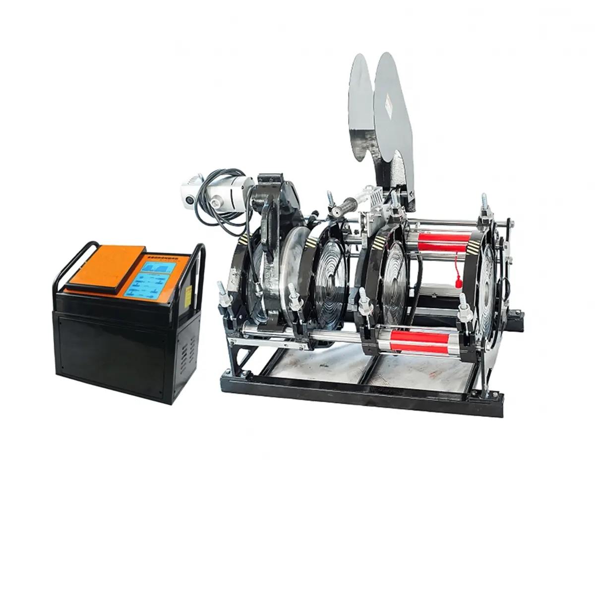
Manual vs. Automatic Welding: SDR Parameter Control
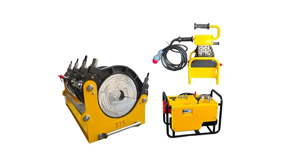
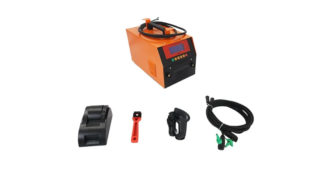
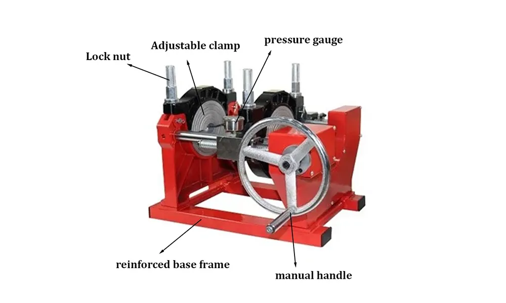
The method of welding also dictates how precisely you can adhere to SDR parameters. Manual butt fusion machines rely heavily on the operator’s skill to interpret pressure gauges and timers, which can introduce variability when switching between SDR 11 and SDR 17 pipes on the same job site. In contrast, CNC automatic butt fusion machines often feature pre-programmed SDR libraries that auto-adjust carriage speed, heater plate engagement, and cooling times, drastically reducing human error.
JQ-Fusion provides a full range of welding equipment from manual to fully automatic systems designed to handle the precise demands of varying SDR classifications. When welding critical gas or water lines, using a machine with data-logging capabilities is recommended to verify that the HDPE pipe welding temperature by SDR protocol was followed exactly.
Validating Your Welding Parameters
Even with the correct temperature and calculated times, the final proof lies in destructive testing and visual inspection. A proper double-bead profile should be uniform, rounded, and free of discoloration. For thicker SDRs, the bead rollback should be symmetrical, indicating that the center of the wall reached melt temperature. For thin SDRs, ensure the bead is present but not so excessive that it risks restricting the internal diameter.
Refer to the ISO 21307 standard for detailed destructive testing protocols, which specify required short-term tensile strength tests that validate whether the chosen SDR-specific welding parameters result in a truly fused, leak-proof system.
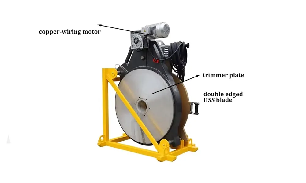
Quick Reference Checklist for Field Welding
- Verify Heater Temp: 420°F-450°F using a calibrated digital thermometer.
- Identify SDR: Select pressure and soak protocol based on actual pipe marking.
- Facing Pressure: Ensure pipe ends form a continuous ribbon before heating, regardless of SDR.
- Dwell Period: Hold the heater against the pipe ends under no pressure to allow heat to permeate according to SDR table.
- Dwell Time: Open the carriage, remove the heater, and close the carriage in < 4 seconds (critical for high SDR).
- Cooling: Maintain pressure until the bead has cooled to ambient temperature. Do not accelerate cooling with water.